


Hi Limits Thermostats:
All Hi Limits are electric switches that OPEN at a pre determined temperature. Check for continuity across the
terminations when the wires are disconnected.
Thermocouples:
Use a Multi Meter capable of measuring DC voltage below 1V. Attach the Negative lead to the Pilot Bracket and
the Positive lead to the upper connection at the Hi Limit. Light the Pilot and measure the DC voltage. The voltage
should be 25-35 mv. If the measured voltage is less than specified, the part should be changed.
Pilots:
Standard:
Pilots must be kept clean and free from anything that might block the flow of gas.
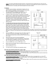
Electronic Ignition: As with Standard pilots, care must be taken to keep this area clean. The Electronic Ignition
Pilot Assembly incorporates the Spark Tip which is encased in a ceramic insulator. Check for any cracks or signs
of damage. Check the spark gap which should be between 3 - 6 mm. The High Voltage wire should also be free
of damage. If the High Voltage Wire is suspected of being at fault it should be checked for continuity.
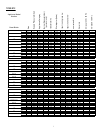
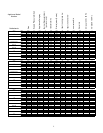
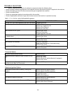
Probes:
Unplug the probe wires at a convenient location and check for resistance. Also check the temperature of the oil. If
the resistance is NOT close to that shown on the chart below it should be changed.
TEMP RESISTANCE TEMP RESISTANCE TEMP RESISTANCE
21.11°C 108051 Ω 79.44°C 11719Ω 148.88°C 1734 Ω
37.77°C 53146 Ω 93.33°C 7586 Ω 162.77°C 1267 Ω
51.66°C 30902Ω 107.22°C 5055 Ω 176.66°C 942 Ω
65.55°C 18695Ω 121.11°C 3458 Ω 190.55°C 712 Ω
76.66°C 12832Ω 135.00°C 2422 Ω 204.44°C 547 Ω
Electronic Ignition Modules:
The module receives a 24 vac signal from the Temperature control system and starts a cycle to light the pilot and
prove the pilot flame. Check the module by following the steps below:
{ Check between the THS Terminal and GROUND for 24 vac to verify that the module is receiving a signal.
{ Listen for a spark sound. If NO spark sound can be heard, Turn the fryer OFF. Unplug the High Voltage Wire from
the module and replace it with a new Electronic Ignition Pilot Assembly. Temporarily ground the Pilot assembly
against a suitable Ground. Turn the machine ON and listen for a spark sound. If a sound can now be heard check
the ground wire on the installed Pilot and repair if damaged. If a spark CAN be heard go to the next step.
{ Check for 24 vac between the two wires at the Pilot solenoid on the Gas Valve. If voltage is found, turn the fryer
OFF and check the Pilot Solenoid for a Resistance of 60 Ohms. If the resistance varies more than 10 Ohms from
normal the Pilot Solenoid is defective and the Gas Valve must be replaced.
{ If the Pilot comes on normally and the Main Burners do NOT, check for 24 vac at the Main Burner Solenoid of the
Gas Valve. If voltage is found, turn the fryer OFF and check the Main Solenoid for a Resistance of 60 Ohms. If the
resistance varies more than 10 Ohms from normal the Main Burner Solenoid is defective and the Gas Valve must
be replaced.
{ If a spark can be heard but it continues without the Pilot lighting check the Flame Sensor as described in the
appropriate section.
Flame Sensors:
Run the fryer and check between the Flame Sensor wire and GROUND for 150 mv. If the millivoltage is NOT
present the Electronic Ignition Module is at fault. Turn the fryer OFF, unplug the wire from the connection on the
sensor. Connect a test meter capable of measuring Microamps in Series with the wire and the Flame Sensor.
Run the fryer so that the Pilot lights. The meter reading should be between 0.15 - 0.35 ma. Remove the meter
and replace the Flame Sensor wire. If the Microamperage is NOT present but the Millivoltage is, the Flame
Sensor is at fault.
Computers:
{ If the computer does NOT have a lit display check for 24 vac between the Green/Yellow and Red wires on the fryer
harness that plugs into the computer harness. If voltage is found, and the display is NOT lit the computer
connections should be checked for integrity. If the connection is good the computer is faulty.
{ If the display is lit but the Main Burners do NOT light, check for 24 vdc at the coil of the K6 relay. This is the Heat
Demand Relay and is switched ON only when the computer calls for a heating cycle. If voltage is present when the
computer is calls for a heat cycle the K6 relay may be at fault. If voltage is NOT present, check the computer
10