


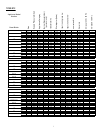
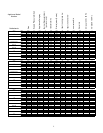
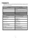
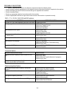
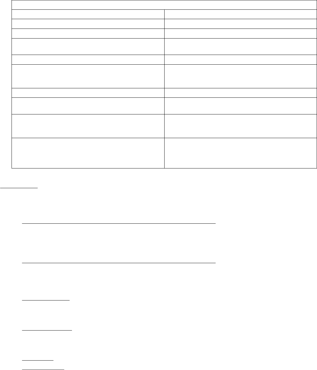
FILTERING SYSTEM:
Check quick disconnect
Check pick up tube is attached correctly
Check paper installation
Check pick up screen installation
Filter pump running
Check power to machine
Check circuit breaker
Check motor overheat trip
Filter pump NOT running
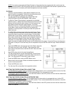
Check the small screen in the end of the pick up tube
(Inside the large steel nut.) to make sure it is clear
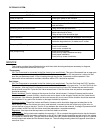
Pick up screen
Paper should be installed per directions in the manualPaper installation
Steel nut should be tight on the filter Pick up screen
inside tube should be clear
Fitting at top of tube should be tight
Pick up tube
Fitting should be tight and cleanShortening return quick disconnect
Remove cap on the left side at the rear of filter and
push red button
Motor overheat trip
Check filter circuit breaker on side of filter handleCircuit breaker
Check main power to the machinePower to machine
CHECKPROBLEM
Check these items before calling your Authorized Service Company
SERVICE
This chapter provides the qualified technician with the trouble shooting techniques necessary to diagnose
individual components within the Pitco fryer.
Thermostats:
GS (The Thermostat is connected to the Gas Valve by two small tubes):
This type of thermostat has an open port
when the temperature at the probe is LESS than the Set temperature. When the temperature is above the Set
level the port becomes closed. If Gas is leaking through the port the Thermostat must be replaced. If the
thermostat will not calibrate or maintain calibration within ±5ºC it should be replaced.
Gas Valves:
GS (The Thermostat is connected to the Gas Valve by two small tubes):
Turn the Pilot Knob the PILOT position.
Remove the Outlet tube from the gas valve actuator. Seal the Outlet port at the gas valve. Turn the Pilot Knob the
ON position. With the Outlet Port sealed the main burners should not come ON, release the seal and the main
burner should come ON. Cycle the Gas Valve several times. If the Gas Valve does not perform as expected it
should be replaced.
Electric Actuated:
Test for Voltage at the wires on the Gas Valve Actuator. If voltage IS present and the valve
Actuator does NOT operate (Usually a small sound can be heard as the Actuator moves) the Gas Valve should
be replaced. If the Actuator operates but the main burners still do not come ON the Actuator should be removed
and inspected. If any part of the Actuator is damaged it should be replaced.
Electronic Ignition:
These Gas Valves use Electric Actuators which should be diagnosed as described in the
above section. These Gas Valves also use a small solenoid, mounted on the side of the body of the valve, to
control the flow of gas to the pilot. Test for 24 vac between the wires at the solenoid, if voltage IS present and NO
gas is evident at the Pilot, the Gas Valve should be replaced as a complete assembly.
Regulators:
Vent caps must be kept clean and free from debris at all times.
Pilot Solenoids:
Using a test meter capable of measuring 0 - 50 mv connect the negative lead to the pilot bracket
and the positive lead to the bottom connection on the hi limit. Light the pilot and allow enough time for the voltage
to increase to a normal level. Turn the Gas Valve Knob to the OFF position and allow the pilot to go out. Listen for
a small noise made when the Pilot Solenoid drops out. The millivoltage reading when this happens should be no
more that 10 mv.
9