3
Medical Package System
compressor to avoid stresses caused
by changes in hot and cold
conditions.
3. Piping supports should be anchored
separately from the compressor to
reduce noise and vibration.
4. Never use any piping smaller than
the compressor connection.
5. Use flexible hose to connect the
outlet of the compressor to the
piping so that the vibration of the
compressor does not transfer to the
piping.
SAFETY VALVES
Tank mounted compressors are
shipped from the factory with safety
valves installed in the tank manifold.
The flow capacity of the safety valve is
equal to or greater than the capacity
of the compressor.
1. The pressure setting of the safety
valve must be no higher than the
maximum working pressure of the
tank.
2. Safety valves should be placed ahead
of any possible blockage point in the
system, i.e. shutoff valve.
3. Avoid connecting the safety valve
with any tubing or piping.
4. Manually operate the safety valve
every six months to avoid sticking or
freezing.
Assembling Modular
Medical System
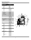
MODULAR PLACEMENT
1. Unpack each module and discard all
wood shipping materials.
2. Locate frame assembly fasteners
provided in parts pack [includes:
fasteners, filter(s), isolation pads and
inlet flex line].
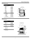
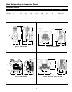
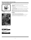
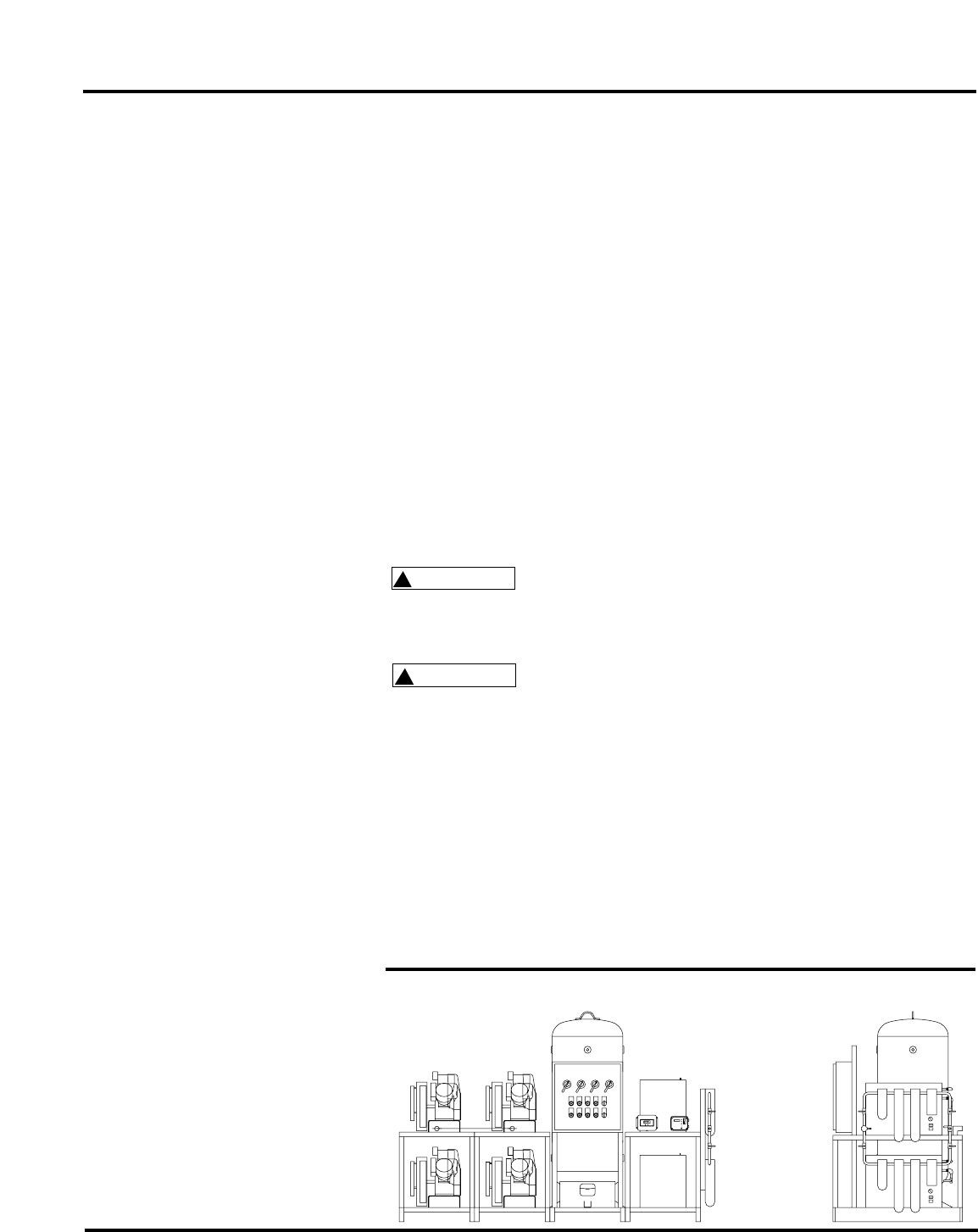
3. Place modules at location designated
(see picture below for proper
arrangment of modules). Provide
sufficient clearance around unit for
servicing (see minimum clearance
section).
4. Install frame assembly fasteners to
each frame joining the frames
together.
5. Lift corners of each frame assembly
and install isolation pads provided.
NOTE: Remove shipping brackets
painted orange located at the base
plate of each compressor module.
This will allow spring isolators to free
up reducing noise and vibration of
the unit.
CONNECTING PIPING
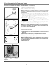
1. Locate connection for piping at rear
of unit for compressors module to
receiver tank module.
2. Remove plastic caps that protect
piping against contamination.
3. Connect flex joint to frame securely
making sure flex line is not pinched
or chinked.
4. Follow steps 1 to 3 for flex line from
dryer package to outlet of receiver
tank.
NOTE: All piping is provided and
sealed for this portion of installation.
5. Locate and attach intake inline air
filter to outside source air or header.
Flex line is provided when attaching
intake of compressors to rigid piping.
6. Connect outlet souce from filter
package located on dryer module to
outlet source piping.
Attach all inlet and
outlet source
piping in accordance with NFPA 99 for
Medical Gas.
ELECTRICAL WIRING OF MODULES
Provide electrical
power in accor-
dance to NEC and local codes. Connec-
tion of wiring should be performed by
a qualified electrician.
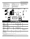
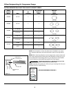
1. Connect wiring and flex conduit
provided from each motor junction
box to correct hole in bottom of
control panel and starter.
2. Connect each temperature switch
from the compressors to contacts
located in control panel as marked
for each temperature switch.
Temperature switches shutdown the
!
CAUTION
!
WARNING
CAL. PORT
CAL. PORT
ZERO CAL.
ZERO CAL.
ALARM
ALARM
SET
SET
ADJ.
ADJ.
PANADRY
PANADRY
F
DEW/FROST POINT
DEW/FROST POINT
PPM
PPM
AUTO CAL
AUTO CAL
CAUTION
CAUTION
ALARM
ALARM
SAFE
SAFE
FLOW
FLOW
compressor when temperature is
above 400°F.
3. Connect wiring of unload solenoids
to contacts located on control panel.
The unload solenoid provides loadless
starting of the compressors on off
cycle.
4. Connect wiring from differential
pressure switch at control panel.
Differential switch wired to contacts
in control panel provided for remote
alarm.
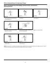
5. Connect wiring from CO Monitor. A
wire set is provided for power and
the other for alarm. Wiring is
marked for easy attachment.
6. Connect wiring from Dew Point
Monitor. A wire set is provided for
power and the other for alarm.
Wiring is marked for easy
attachment.
7. Dryer(s) need a separate properly
protected power supply for each
dryer. Standard voltage is 110 Volts.
Other voltages are available. Check
for voltage of dryer supplied and
current rating provided on data plate
of dryer.
NOTE: Units provided with desiccant
drying systems are wired directly to
the control panel provided.
For questions concerning assembling
and start-up, contact Powerex at 1-800-
544-0350 for technical assistance.
Operation
Powerex package medical system
operates at a maximum pressure of 100
PSIG. Compressor RPM’s are established
by Powerex based on horsepower and
operating pressure.
MPD Medical
Package System


