


2
IMPORTANT CORD AND PLUG INFORMATION
A short power supply cord (or cord set) is provided to reduce the risk resulting from becoming entangled in or tripping over a longer
cord. DO NOT USE WITH AN EXTENSION CORD.
Do not allow the cord to run underneath or around the unit. The magnetic cord may not detach easily if the cord is positioned in this
fashion.
Connect the power supply cord to a polarized outlet only. As a safety feature, this appliance has a polarized plug (one blade is wider than
the other). This plug will only fit in a polarized outlet one way. If the plug does not fit fully in the outlet, reverse the plug. If it still does
not fit, contact a qualified electrician. Do not attempt to defeat this safety feature.
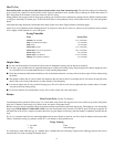
How to Install Legs and Handles
Tools Required: Phillips type screwdriver
Parts Included: 4 Legs
2 Handles
To Install Legs
1. Place multi-cooker upside down on table or counter.
2. Using the screwdriver, remove the screws from each of the four mounting projections on the bottom of the unit. These screws are for
attaching the legs to the multi-cooker base.
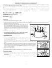
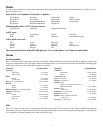
3. Position one of the legs, with the rubber insert facing up, over
one of the mounting projections (Fig. A). Align the hole in
the leg with the hole in the mounting projection and fasten
securely with screw. Leg should not rock or move if twisted.
Caution: Overtightening can result in stripping of screws or cracking
of legs.
4. Repeat step 3 for other three legs.
5. Turn multi-cooker right side up on table or counter. When properly
assembled, the multi-cooker should sit level with no leg rock.
To Attach Handles to Base
1. With multi-cooker upside down on table or counter, remove the screws
from the tabs on each side of the multi-cooker base. These screws are
for attaching the handles to the base.
Hint: When removing the screw under the heat control receptacle,
hold the screwdriver at a slight angle or use a short screwdriver or a screwdriver with a long
shank.
2. Slide one of the handles, with the screw hole facing up, onto the tab so the screw hole on the tab
aligns with the screw hole on the handle (Fig. A). Fasten with screw and tighten fully. Handle
should not wobble or move when grasped. Caution: Overtightening can result in stripping of
screws or cracking of handles.
3. Repeat step 2 for other handle.
4. When properly installed, the handles should appear level with the table or counter.
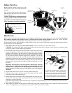
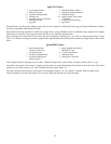
To Attach Basket Handle
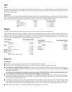
1. Slide lock bar up on handle (Fig. B) and place one of the handle bars into one of the tabs on
bracket. Then squeeze the handle bars together, and fit the other handle bar into the opposite
tab on bracket.
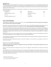
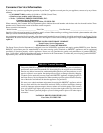
2. After attaching handle to basket, slide the lock bar down (Fig. C) to insure against accidental
detachment of handle from basket.
Leg
Mounting
projection
Screw
Rubber
insert
Handle
Tab
Screw
Tab
Screw
hole
Fig. A
Heat
control
receptacle
Lock bar
Lock bar
Fig. C
Fig. B
Tab
Handle bar