


- 11 -
10. INSTALL THE HOOD (ALL BLOWERS)
HD0265
A
B
A
B
B
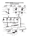
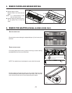
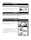
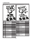
INTERNAL BLOWER: Run power cable to installation location. Place the hood in its location. Mark the position of the screws
(smaller part of the key holes [A]) with a pen. Remove the hood and install the (4) 1/2” double thread screws at marked positions,
leaving a 1/8” gap. Remove wiring cover. Insert the cable in the hood through the wire clamp and tighten the wire clamp to secure
the cable. Place the hood under the cabinet and slide it into position. Make sure the adapter (or the transition) enters the ducting.
Secure the hood by tightening the screws completely. Install the last 1/2” double thread screws in the remaining holes [B].
EXTERIOR OR IN-LINE BLOWER: Run power cable to installation location. Place the hood in its location. Mark the position of
the screws (smaller part of the key holes [A]) with a pen. Remove the hood and install the (4) 1/2” double thread screws at
marked positions, leaving a 1/8” gap. Remove wiring cover on top of the hood, punch-out the electrical knock-out and install the
wire clamp. Insert the cable in the hood through the wire clamp and tighten the wire clamp to secure the cable. Connect wiring
(see instructions included with exterior or in-line blower). Place the hood under the cabinet and slide it in position. Secure the
hood by tightening the screws completely. Install the last 1/2” double thread screws in the remaining holes [B].
INTERNAL BLOWER HOOD
EXTERIOR OR IN-LINE BLOWER HOOD
11. CONNECT WIRING (ALL BLOWERS)
WARNING
Risk of electrical shock. Electrical wiring must be done by qualified personnel in accordance with all
applicable codes and standards. Before connecting wires, switch power off at service panel and lock
service disconnecting means to prevent power to be switched on accidentally.
!
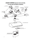
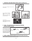
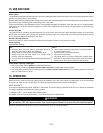
Remove wiring cover from rough-in plate or electrical compartment and set
aside.
INTERNAL BLOWERS: Connect cable into wiring box using wire connectors.
Connect BLACK to BLACK, WHITE to WHITE and
GREEN or bare wire under GREEN ground screw.
Reinstall wiring cover.
IN-LINE OR EXTERIOR BLOWERS: See instructions included with blower.
CAUTION
The ORANGE wire (A) is for make-up air device connection only.
If there is no make-up air device, never remove the cap on the
ORANGE wire end.
HE0088
A
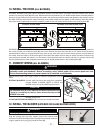
WARNING
Do not plug the two cords together.
!
Plug the 3-prong plug cord from rough-in plate to the 3-prong male
connector inside the hood (A) and the 2-prong male connector cord from
rough-in plate to the 2-prong plug inside the hood (B).
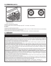
12. INSTALL THE BLOWER (EXTERIOR OR IN-LINE BLOWER HOOD)
A
B
HE0078