104
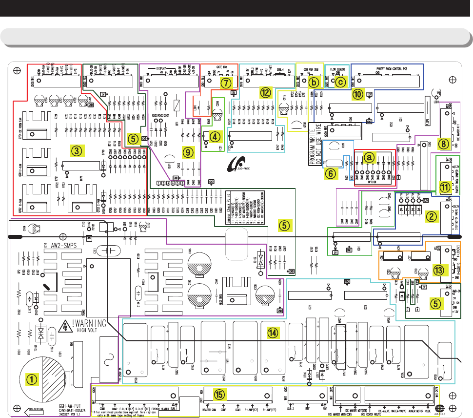
PCB DIAGRAM
6-1) PCB Layout with part position
1. DC13V, 5V, GND supplied from SMPS PCB
2. Circuit for controlling Step-Valve (3-Way Valve) * Option
3. FAN MOTOR control part : To supply the power from 8.3V ~ 12V according to the motor types. (F,R,C,ICE)
4. EEPROM : Save and record every kinds of data.
5. Transmit inputted signals from every sensor into MICOM after eliminate the noise.
6. Micom : control the regrigerator Ceramic resonator : generate the basic frequency of Micom operation.
Reset IC : make Micom reset if input voltage of Micom is detected less than the specified voltage
7. PLC input/output
- PLC (Power Line communication) * Option(PLC module is not inserted unless specified occasion)
8. Operate ICE-MAKER, supply power to MOTOR, and sense the variation of switch.
9. Main Micom
Panel Micom serial communication circuit
- Dispenser option input part (Water & Cover Ice route switch)
10. Pantry room display control part : display LED, detect KEY state.
11. Control Pantry room damper & Damper heater
12. Water Tank Heater Controls (also controls other options)
13. LED LAMP Control Circuit (F, R LAMP) * Option
14. Relay parts that controls AC load and receives Micom operating signal through Sink IC.
15. Connector with AC load
a. Diode option setting area
b. Inverter COMP controlling signal
c. Sensing part of Flow Sensor.


