-30-
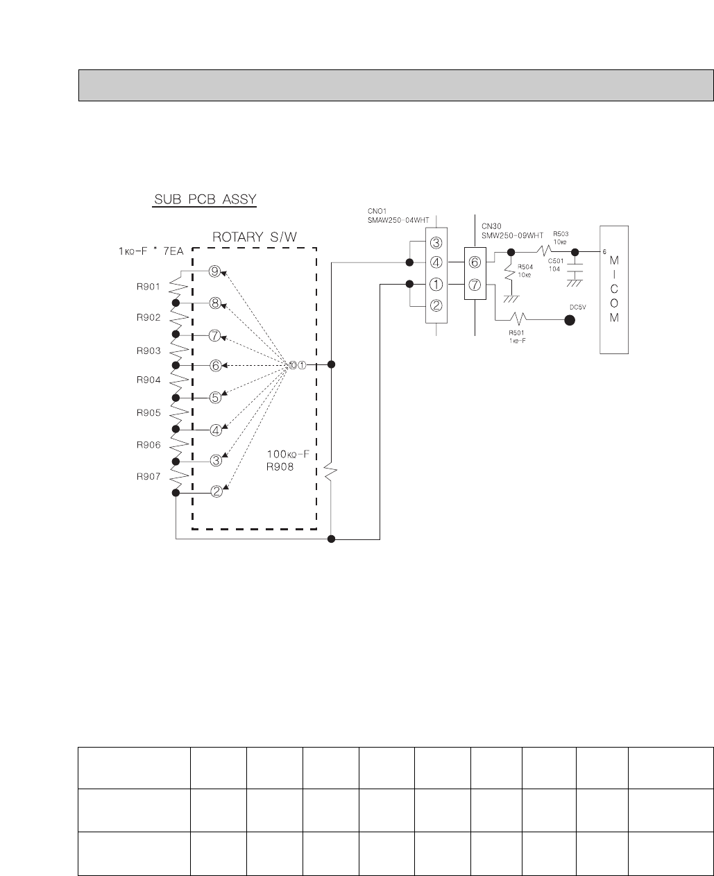
9-5. TEMP. CONTROL CIRCUIT.(ROTARY S/W)
A. FREEZER TEMP.
※CAUTION
It is appeared the S/W cross spot of ROTARY
S/W circuit ①∼⑩
Temp. control is changed KNOB of contructed ROTARY S/W in the freezer and it is possible the temp. control 1 step
to 8 step.
Temp. control SETTING become partial pressure for R 501 resistance and ROTARY S/W resistance.
(Row composition resistance of resistance charge to R 908 and ROTARY S/W direction)
And partial pressure is delivered to MICOM through R 503 resistance and recognited temp. control and it become
SETTING to temp. contol.
Voltage or resistance charge of MAIN PCB MICOM input for SUB PCB Ass’s ROTARY S/W cross spot direction is
same the below.
(When Measure the resistance charge, connector of MAIN PCB CN 30 is separated and measure the connector
terminal.)
※ To upside, when measure the resistance charge isn’t appeared the resistance in the case SUB PCB ASSY
connection is disconnection or crack situation of PCB board.
Section
Voltage
(R504)
Resistance
(CN30⑥~⑦)
1 STEP
(9PIN)
2.77
±0.15V
6.54㏀±
1%
2 STEP
(8PIN)
2.94
±0.15V
5.66㏀±
1%
3 STEP
(7PIN)
3.12
±0.15V
4.76㏀±
1%
4 STEP
(6 PIN)
3.33
±0.15V
3.84㏀±
1%
5 STEP
(5 PIN)
3.57
±0.15V
2.91㏀±
1%
6 STEP
(4 PIN)
3.84
±0.15V
1.96㏀±
1%
7 STEP
(3PIN)
4.16
±0.15V
0.99㏀±
1%
8 STEP
(2 PIN)
4.54
±0.15V
0Ω
WHEN OPEN
THE OPEN SPOT
0.1~ 0.7V
100㏀±1%


