C.C.
C.C.
C.
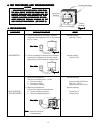
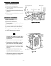
REMOVING BLOWER MOTORREMOVING BLOWER MOTOR
REMOVING BLOWER MOTORREMOVING BLOWER MOTOR
REMOVING BLOWER MOTOR
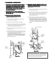
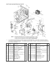
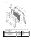
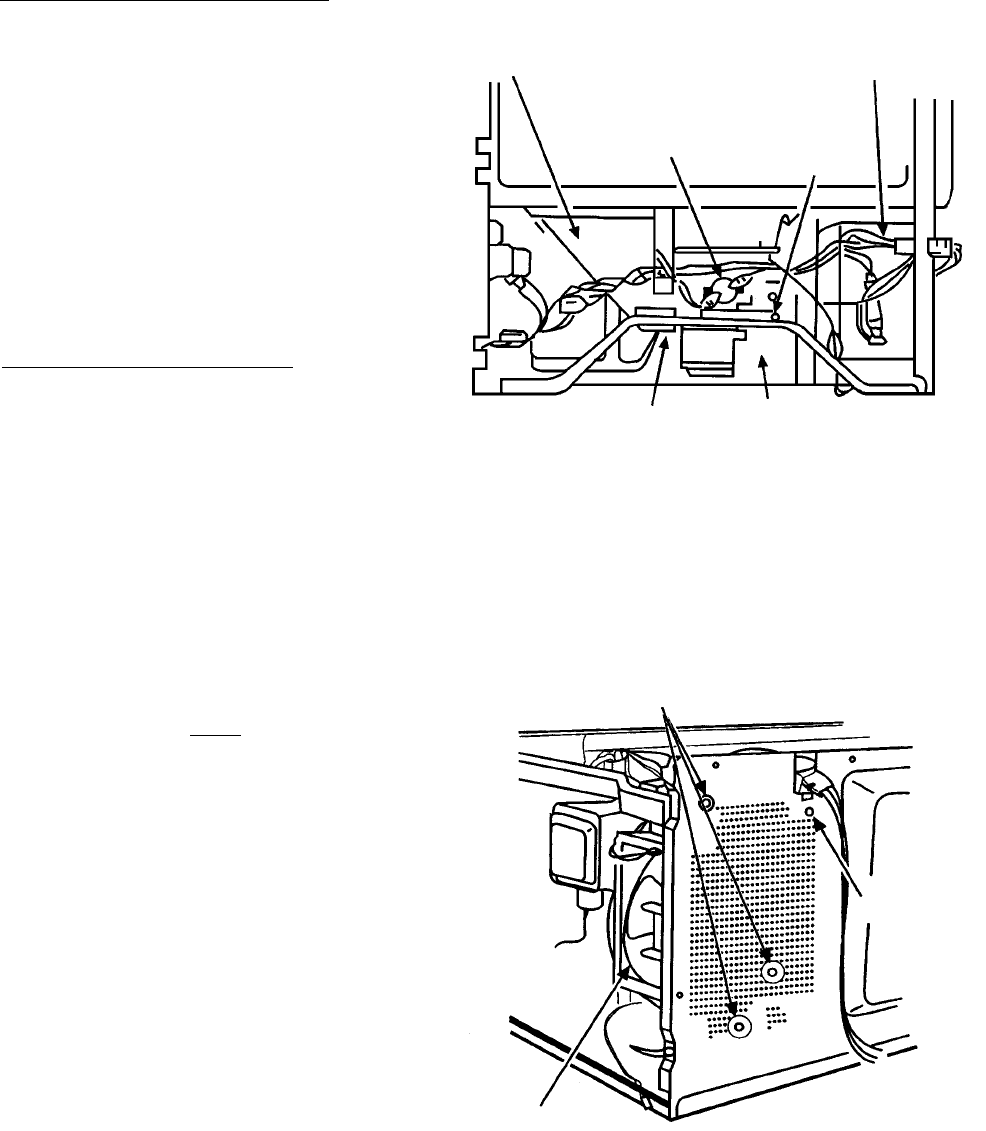
(Figures 11 (Top View) and 12).
(1) Remove screw securing the stay.
(2) Disconnect all lead wires from the blower motor
and H.V. capacitor.
(3) Remove 3 screws securing the blower base and
disengage 3 hooks from the rear plate of cavity
(Figure 12).
(4) Remove 1 screw securing the blower motor with
the blower base.
D.D.
D.D.
D.
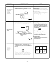
REMOVING MAGNETRONREMOVING MAGNETRON
REMOVING MAGNETRONREMOVING MAGNETRON
REMOVING MAGNETRON
(Figure 11 (Top View))
After removing the blower motor :
(1) Remove duct (mag. exhaust). Remove the screw
securing the stay.
(2) Remove 1 screw securing the thermal protector.
(3) Disconnect 2 lead wires from the magnetron.
(4) Remove 4 screws securing the magnetron to the
waveguide.
(5) Take out Magnetron VERY CAREFULLY.
NOTENOTE
NOTENOTE
NOTE
1. When removing the magnetron from the cavity or
wave guide, use a proper care so that the dome of
the magnetron does not hit any adjacent parts of
microwave oven.
2. Make sure that the contact face of the magnetron
gasket is free from any damage or deformation.
3. Adjust the position of the magnetron properly, so
that it correctly sits in place and the magnetron
gasket is in contact with the mounting rim evenly.
4. While holding the magnetron under this condition,
tighten mounting screws or nuts with your fingers
temporarily.
5. Further tighten the screws or nuts with a box
wrench, giving one or two turns to each of the
screws (or nuts) alternatively so that the
magnetron is mounted on to the bracket uniformly.
6. After replacing the magnetron, be sure to check the
microwave energy leakage with a leakage detector
and confirm the leakage is below 4mW/cm
2
.
- 12 -
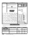
Duct (mag. exhaust)
Thermal Protector
Blower Base
Screw
Duct (mag. intake)
Stay
FigurFigur
FigurFigur
Figur
e 11 (Te 11 (T
e 11 (Te 11 (T
e 11 (T
op Vop V
op Vop V
op V
iew)iew)
iew)iew)
iew)
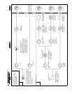
Figure 12Figure 12
Figure 12Figure 12
Figure 12
Hook
Blower Motor
Screw


