


8
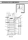
REFRIGERATOR COMPONENTS
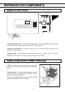
1. Front cover: Open this cover when connecting the remote alarm or replacing glow starter for
fluorescent lamp.
2. Control panel: Panel can be opened when upper right corner of the lower part cover is pushed.
Refer to page 10.
3. Automatic temperature recorder: A 7-day type recorder is provided. For proper usage of the
recorder, see the instruction manual enclosed with the unit.
4. Access port: This port allows temperature measurement cables to enter the chamber from outside.
A total of two (2) ports are provided; left side and right side.
5. Glass window: The window may have condensation in high humidity environment. Wipe off the
condensation with a soft dry cloth.
6. Lock: Turn the key counterclockwise through 180
o
to securely lock the door.
7. Handle: Always hold the handle when opening/closing the door.
8. Fluorescent lamp: 20 W lamp. See page 19 for replacement.
9. Light switch: This switch is used for turning the fluorescent lamp off and on.
10. Air vent – front intake: Do not block this vent. If this vent is blocked, temperature regulation will
become unstable. Do not insert a finger or any foreign object into this vent as there is danger from the
internal fan.
11. Air vent – rear exhaust: Do not block this vent. If this vent is blocked, temperature regulation will
become unstable. Do not place stored items in the path of the cold air.
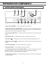
12. Drawer (MBR-704GR only): Items to be stored in the chamber must be placed on the drawers.
The maximum storage weight for each drawer is 40 kg.
Shelf (MBR-704G only): Items to be stored in the chamber must be placed on the shelves. The
maximum storage weight for each shelf is 40 kg.
Do not put stored items directly onto the interior floor of the chamber. See page 14.
13. Leveling foot: Adjust the height of the leveling foot by turning the screw bolt until the unit is level.
14. Castors: When installing the unit the castors can be raised from the ground by using the leveling
feet above.
15. Inner door
16. Upper monitor bottle
17. Lower monitor bottle
18. Door switch: The switch detects the door condition (open or close).
19. Condensation tray: The condensation on the door is accumulated in this tray. Wipe off the water
occasionally.
20. Power switch (back side): Switch for the refrigerator. This switch also acts as an over-current
breaker (10A).
21. Fixtures (back side): These keep the adequate space between the unit and wall and also can be
used for fixing the unit. See page 12.
22. Evaporating tray (back side): Defrost water from the evaporator accumulates on the tray and
evaporates into the atmosphere. See page 18 for cleaning.
23. Bottom air duct (MBR-704G only): The duct keeps temperature inside the chamber uniformly by
making cooled air circulate. Put the duct at the bottom of the chamber. Do not put any articles under
this duct. If this duct is blocked, temperature regulation will become unstable.