


- 51 -
9
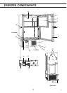
FREEZER COMPONENTS
1. Outer door: To open the outer door, grip the handle. On closing, lock the outer door latch
completely.
2. Inner door: The operation of the inner door should be quick to minimize the temperature rise in
chamber. Lock the inner door latch completely when the inner door is closed. The inner door is
removable for cleaning or defrosting. See page 21 “Routine maintenance”.
3. Inner door latch: Always lock the inner door latch when the inner door is closed.
4. Outer door latch: Always lock the latch when the outer door is closed.
5. Magnetic door gasket: This provides a tight door seal and prevents cold air leak. Keep clean.
6. Air intake vent (grille): Do not block this vent to keep the proper cooling performance.
7. Caster: 4 casters are provided to facilitate moving of the cabinet. For the installation, adjust the
leveling foot so that the front 2 casters cannot contact with the floor.
8. Leveling foot: These are screw bolts used to install and fix the unit. Adjust the height of the
leveling feet by turning the screw bolts until 2 front casters are away from the floor.
9. Condenser filter (behind the grille): This filter prevents the dust from accumulating on the
condenser. The dusty filter may cause failure of refrigerating device. Clean the filter once a month.
See page 20 “Routine maintenance” for the cleaning.
10. Space for temperature recorder: A temperature recorder (optional component) can be attached
here. See page 27 “Temperature recorder”.
11. Lock: Turn clockwise to 180
o
with a key and the outer door is securely locked.
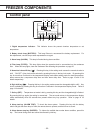
12. Control panel: Used for temperature setting and indication of operating status is displayed on the
panel. See page 10 for details.
13. Access port (rear and bottom): This is used for leading a cable and sensor of a measuring
equipment, or nozzle of back-up system to chamber.
14. Air intake port: After closing the outer door, if used to open soon. See page 17
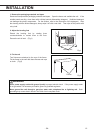
15. Fixture (on back side): 2 fixtures serve as spacers between the cabinet and wall and also serve as
hooks to fix the unit. See page 12 “Installation”.
16. Power switch: This is for turning ON/OFF the power to the unit. ON – “I” OFF – “ṯ”
17. Remote alarm terminal: This is used to notice an alarm condition of the unit to remote location.
Refer to page 17 “Remote alarm terminal”.
18. Battery switch: This is a switch for a battery for power failure alarm. Normally, turn on this switch.
Be sure to turn off this switch if the freezer is not in operating for the long period.
19. Fuse: 125 V, 3.15 A. Normal blow type.