


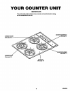

INSTALLATION
IMPORTANT: Leave these instructions
with the appliance.
OWNER: Keep these instructions for
future use.
TOOL LIST
The following tools are needed to Install your new
counter unit.
Pipe wrenches
Flat bladed screwdriver
• Rule or tape measure and straightedge
• Hand saw or saber saw
ADDITIONAL MATERIALS
• Gas supply line shut-off valve
• Pipe joint sealant (resistant to L.P. gas)
J
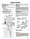
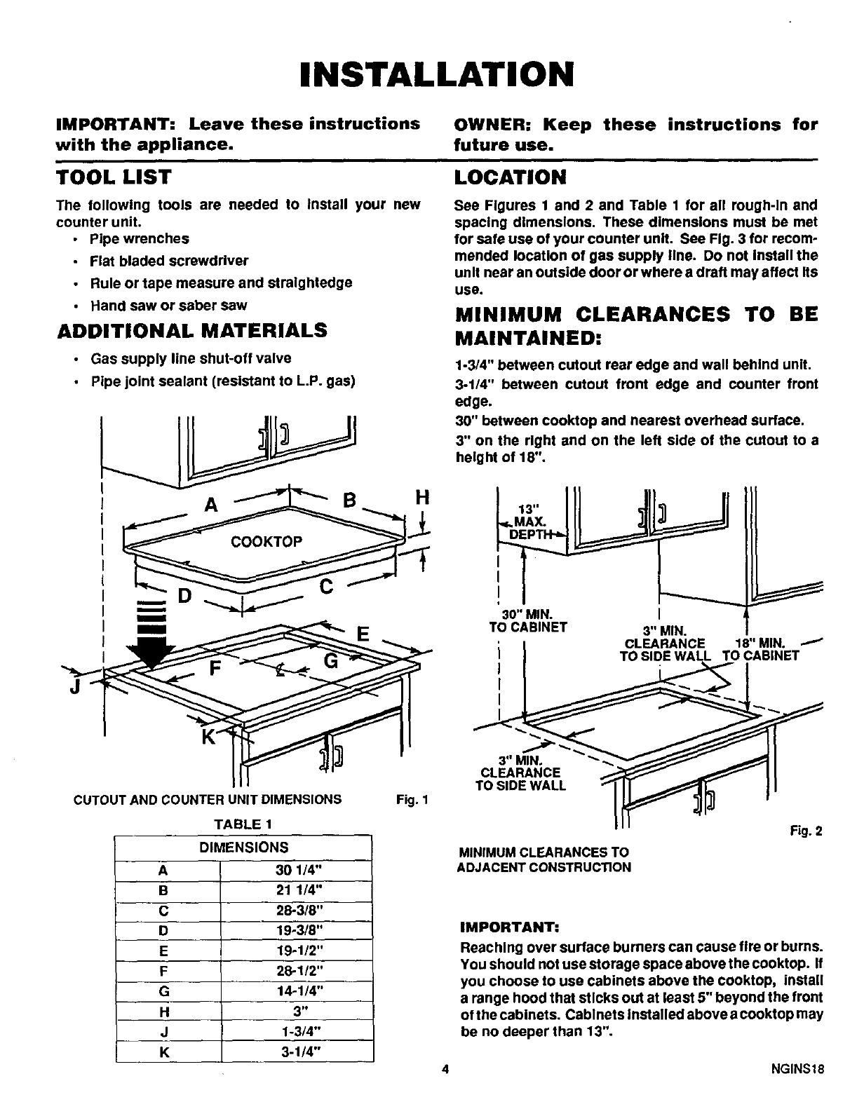
CUTOUT AND COUNTER UNIT DIMENSIONS Fig. 1
A
B
C
D
E
F
G
H
J
K
TABLE 1
DIMENSIONS
30 1/4"
21 1/4"
28-3/8"
19-3/8"
19-1/2"
28-1/2"
14-1/4"
3"
1-3/4"
3-1/4"
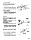
LOCATION
See Figures 1 and 2 and Table 1 for all rough-In and
spacing dimensions. These dimensions must be met
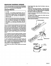
for safe use of your counter unit. See Fig. 3 for recom-
mended location of gas supply line. Do not Install the
unit near an outside door or where a draft may affect Its
use.
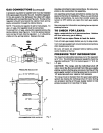
MINIMUM CLEARANCES TO BE
MAINTAINED:
1-3/4" between cutout rear edge and wall behind unit.
3-1/4" between cutout front edge and counter front
edge.
30" between cooktop and nearest overhead surface.
3" on the right and on the left side of the cutout to a
height of 18".
30" MIN. I
TO CABINET 3" MIN.
CLEARANCE 18" MIN. I"
TO SIDE WALL .TO CABINET
CLEARANCE _ // I I
" ' Fig. 2
MINIMUM CLEARANCES TO
ADJACENT CONSTRUCTION
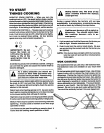
IMPORTANT:
Reaching over surface burners can cause fire or burns.
You should not use storage space above the cooktop. If
you choose to use cabinets above the cooktop, install
a range hood that sticks out at least 5" beyond the front
of the cabinets. Cabinets Installed above a cooktop may
benD deeperthan 13".
4 NGINS18