


17
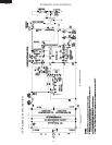
MMD24S
MMD24B
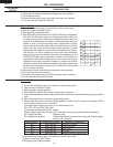
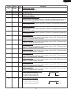
I SECONDARY INTERLOCK SWITCH TEST
STOP SWITCH
1. Disconnect the power supply cord.
2. Open the drawer and keep it open.
3. To discharge high voltage capacitor, wait for 60 seconds.
4. Isolate the switch and connect the ohmmeter to the common (COM.) and normally open (NO)
terminal of the switch. The meter should indicate an open circuit with the drawer open and a closed
circuit with the drawer closed. If improper operation is indicated, replace the stop switch.
5. Reconnect all leads removed from components during testing.
6. Reassemble the unit.
7. Reconnect the power supply cord.
8. Run the oven and check all functions.
NOTE: If the stop switch contacts fail in the open position and the door is closed, the cooling fan motor,
stirrer motor and oven light will be activated by RY1.
J STOP SWITCH TEST
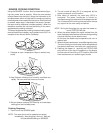
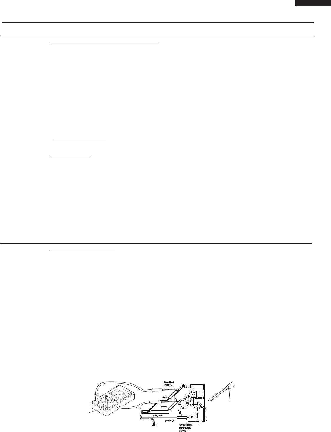
K MONITOR SWITCH TEST
1. Disconnect the power supply cord.
2. Open the drawer and keep it open.
3. To discharge high voltage capacitor, wait for 60 seconds.
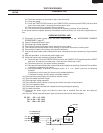
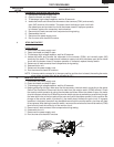
4. Before performing this test, make sure that the secondary interlock switch, according to the above
Switch Test Procedure. Disconnect the wire lead from the monitor switch (COM) terminal. Check
the monitor switch operation by using the ohmmeter as follows. When the drawer is open, the meter
should indicate a closed circuit. When the monitor switch actuator is pushed by a screw driver through
the lower latch hole on the front plate of the oven cavity with the drawer opened (in this condition the
plunger of the monitor switch is pushed in), the meter should indicate an open circuit. If improper
operation is indicated, the switch may be defective and both the monitor switch, plus fuse will need
to be replaced. After testing the monitor switch, reconnect the wire lead to the monitor switch (COM)
terminal and check the continuity of the monitor circuit.
5. Reconnect all leads removed from components during testing.
6. Reassemble the unit.
7. Reconnect the power supply cord.
8. Run the oven and check all functions.
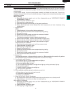
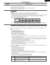
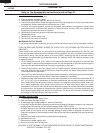
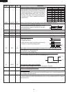
TEST PROCEDURES
PROCEDURE
LETTER
COMPONENT TEST
MONITOR
SWITCH
INTERLOCK
SWITCH
SECONDARY
(BLK)
(BRN,GRY)
(BRN,BLK)
(RED)
Screw Driver
Ohmmeter
1. Disconnect the power supply cord.
2. Open the drawer and keep it open.
3. To discharge high voltage capacitor, wait for 60 seconds.
4. Isolate the switch and connect the ohmmeter to the common (COM.) and normally
open (NO) terminal of the switch. The meter should indicate an open circuit with
the drawer open and a closed circuit with the drawer closed. If improper operation
is indicated, replace the secondary interlock switch.
5. Reconnect all leads removed from components during testing.
6. Reassemble the unit.
7. Reconnect the power supply cord.
8. Run the oven and check all functions.