


19
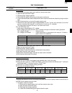
R-1480
R-1481
R-1482
TEST PROCEDURES
PROCEDURE
LETTER
COMPONENT TEST
1. Disconnect the power supply cord, and then remove outer case.
2. Open the door and block it open.
3. Discharge high voltage capacitor.
4. Disconnect the leads to the primary of the power transformer.
5. Ensure that these leads remain isolated from other components and oven chassis by using insulation
tape.
6. After that procedure, re-connect the power supply cord.
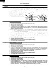
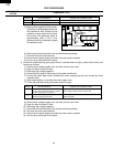
7. Remove the outer case and check voltage between Pin No. 7 of the 4 pin connector (A) and the
common terminal of the relay RY1 on the control unit with an A.C. voltmeter.
The meter should indicate 120 volts, if not check oven circuit.
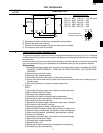
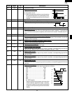
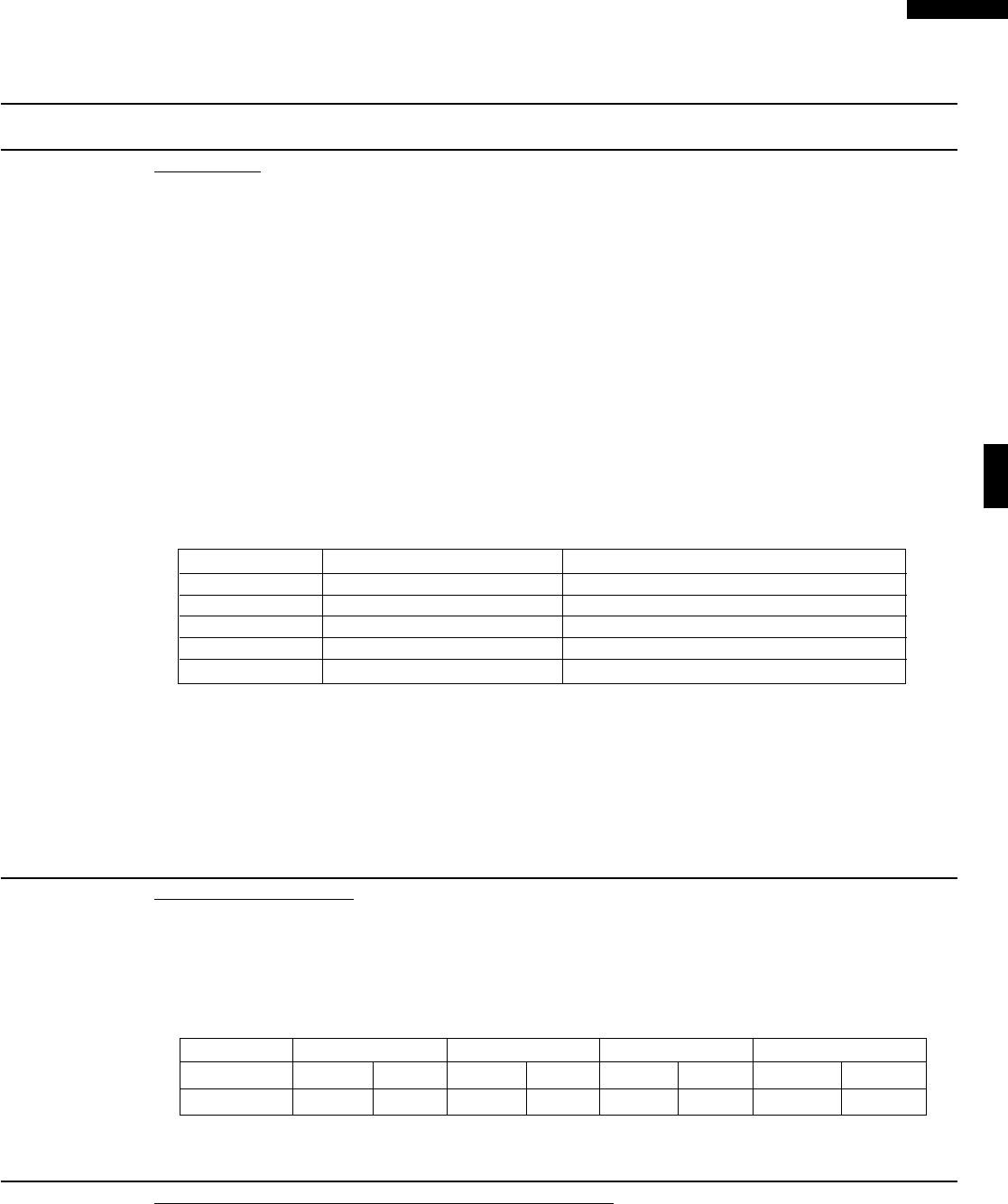
RY1 and RY2 Relay Test
These relays are operated by D.C. voltage
Check voltage at the relay coil with a D.C. voltmeter during the microwave cooking operation.
DC. voltage indicated ................... Defective relay.
DC. voltage not indicated ............. Check diode which is connected to the relay coil. If diode is
good, control unit is defective.
RELAY SYMBOL OPERATIONAL VOLTAGE CONNECTED COMPONENTS
RY1 Approx. 24.0V D.C. Oven lamp / Fan motor / Stirrer motor
RY2(COOK) Approx. 24.0V D.C. Power transformer
RY3 Approx. 24.0V D.C. Turntable motor
RY4 Approx. 24.0V D.C. Hood motor
RY5 Approx. 24.0V D.C. Hood motor (HIGH /LOW selection)
8.Disconnect the power supply cord, and then remove outer case.
9.Open the door and block it open.
10.Discharge high voltage capacitor.
11.Reconnect all leads removed from components during testing.
12.Re-install the outer case (cabinet).
13.Reconnect the power supply cord after the outer case is installed.
14.Run the oven and check all functions.
N RELAY TEST
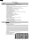
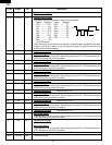
O COMPU DEFROST TEST
(1) Place one cup of water in the center of the turntable tray in the oven cavity.
(2) Close the door, touch the " COMPU DEFROST " pad once and touch the Number pad "1" and touch
the Number pad "5". And then touch the "START" pad.
(3) The oven is in Compu Defrost cooking condition.
(4) The oven will operate as follows
WEIGHT 1ST STAGE 2ND STAGE 3RD STAGE 4TH STAGE
LEVEL TIME LEVEL TIME LEVEL TIME LEVEL TIME
0.5lbs 70% 35sec. 0% 40sec. 50% 30sec. 30% 35sec.
(5) If improper operation is indicated, the control unit is probably defective and should be checked.
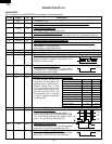
To protect the electronic circuits, this model is provided with a fine foil pattern added to the primary on
the PWB, this foil pattern acts as a fuse.
1. Foil pattern check and repairs.
1) Disconnect the power supply cord, and then remove outer case.
2) Open the door and block it open.
3) Discharge high voltage capacitor.
4) Follow the troubleshooting guide given below for repair.
P FOIL PATTERN ON THE PRINTED WIRING BOARD TEST