


4
FRONT PANEL FEATURES
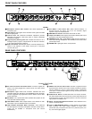
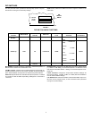
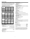
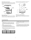
MODEL SCM810 FRONT PANEL
FIGURE 1
ᕡ Microphone Channel Gain Controls 1–8: Allows adjustment of
microphone gain.
ᕢ Input LED 1–8: Lights green when channel is active; lights red at 6 dB
below clipping level.
ᕣ Low-Cut Filter 1–8: Recessed screwdriver adjustment provides
adjustable low-frequency rolloff (high pass) to reduce undesirable
low-frequency signals.
ᕤ High-Frequency Shelving Filter 1–8: Provides level boost or cut in
mid/high-frequency region to compensate for off-axis tone coloration,
or for cutting high-frequency sibilance.
ᕥ AUX Level Control: Sets the input level for aux-level equipment con-
nected to the adjacent 1/4-inch INPUT phone jack or rear-panel
1/4-inch AUX input.
ᕦ Aux INPUT 1/4-inch Phone Jack: Mixes external auxiliary- or
line-level sources into output. This out is not automatic. Signal
appears at output of all linked mixers.
ᕧ MASTER Level Control: Determines the overall mix level.
ᕨ Output Level Meter: Nine-segment LED meter indicates peak output
signal level. Last LED indicates limiter action.
ᕩ PHONES Control and 1/4-inch Phone Jack: Permits monitoring of
mixer output through headphones. The PHONES knob controls head-
phones output level.
µ POWER LED: Lights green when unit is powered.
REAR PANEL FEATURES
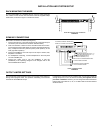
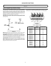
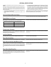
SCM810 REAR PANEL
FIGURE 2
¸ AC Power Connector and Rocker Switch: Connector supplies AC
power to unit when plugged into a power source: the rocker switch
turns the unit on.
¹ Microphone Logic: DB-25 male connector interfaces with each
channel's GATE OUT, MUTE IN, and OVERRIDE IN logic terminals.
See the Suggested Logic Applications section. NOTE: THIS IS NOT
AN RS-232 PORT.
Ƹ DIP Switch: The 7-position DIP switch provides setup options for the
mixer (see DIP Switches section).
ƹ LINK IN/OUT Jacks: Allow multiple mixers to be stacked for addi-
tional inputs. Up to 50 SCM810 mixers can be linked.
ƺ LINE OUTPUT Removable Block Connector: Active balanced
line-level signal for connection to amplifiers, recorders or other mixers.
Output can be modified to microphone level (see Internal
Modifications).
ƻ DIRECT OUT 1/4-inch Phone Jacks: Provides non-gated aux-level
signal from each channel. Direct outs are wired pre-fader and pre-EQ.
Can be modified for use as a gated channel output, send/receive
insert point, or external speech gate for mixing consoles (see Internal
Modifications section).
Ƽ AUX/D.O./D.O. Switch: Located behind the Line Output connector,
this switch selects either aux input function or direct output function for
channel 8 Direct Out jack. Left switch position is AUX IN; center and
right positions are DIRECT OUT.
ƽ INPUT 1–8 Removable Block Connectors: Active balanced micro-
phone- or line-level inputs.
ƾ Input 1–8 MIC/PHM/LINE Switch: Located behind the removable
block connector, this switch selects operation at either micro-
phone-level (left), microphone-level with 48 V phantom power (cen-
ter), or line-level (right) signals.
ᕡ
ᕢ
ᕣ
ᕤ
ᕥ
ᕦ
ᕧ
ᕨ
ᕩ
µ
¸
¹Ƹ
ƹ
ƺƻƼƽ
ƾ