Impinger I – Adv Digital – Gas Service Manual – International
7
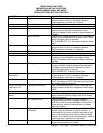
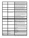
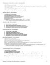
WITH POWER OFF: Remove 3 prong plug (on gas
valve) and measure continuity between terminals 2 and
3. If no continuity, check the following: Proper gas
pressure supply to gas valve as marked on the oven
specification plate. Check for proper adjustment of the
gas pressure switch, 10 for Nat. gas, 27 for LP gas or
4.5 for town gas. Check the filter in the gas valve for
blockage or damage. If above checks are okay, but
pressure switch is still not closed, replace gas valve.
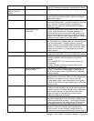
Ignition control Check for supply voltage to ignition control at terminal
#1 and neutral. If no voltage is present, trace wiring back
to gas pressure switch. If voltage is present, check for
supply voltage to burner blower motor at terminal #6 and
neutral. If no voltage is present, wait 30 seconds, reset
ignition control, and re- try. If the above fails, replace
ignition control.
Burner reset switch Switch is normally open. Check to see that the switch
closes when reset button is pushed. Replace as needed.
Burner blower motor Check for supply voltage to burner blower motor. If no
voltage is present, trace wiring back to the ignition
control.
WITH POWER OFF: Turn blower wheel to check for
locked rotor.
If supply voltage is present and motor does not run,
replace burner blower motor.
Burner blower motor air
pressure switch
Check for supply voltage switching to terminal NO as the
air pressure switch closes. Check for air tube blockage
or misalignment, adjust air pressure switch. If the above
fails, replace air pressure switch.
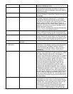
Spark generator After a pre-purge time of 30 to 60 seconds after burner
blower motor starts, check for supply voltage to spark
generator. If voltage is not present, check burner reset
switch. If voltage is still not present, replace ignition
control. If voltage is present, visually check for spark at
igniter.
Igniter/sensor assembly Check for visible damage to the igniter/sensor assembly.
If there is no visible damage to the components, and no
spark, replace the spark generator. If there is visible
damage to the igniter/sensor assembly, replace. Also
check for frayed or damaged wires in burner tube.
Gas valve Check for supply voltage to gas valve. If no voltage is
present, check reset button. Check all connections for
tightness. If there is still no voltage at the gas valve,
replace ignition control. If there is voltage present, check
for gas pressure at gas pressure tap located in gas
piping. If there is no gas pressure, replace gas valve.
Flame will not stay on Flame sensor Check for flame sensor operation, connect a digital
multimeter (capable of measuring DC microamps)
between the flame sensor wire and terminal #1 on the
ignition control. Sensor current is to be 3 microamps,
minimum. If these readings are not achieved, replace
igniter/sensor assembly. Also check for any type of
damage to flame sensor wire and connections.
NOTE: The DC microamp test must be conducted with
the oven in low flame (bypass) operation.
Power supply Set the temperature to the lowest temperature setting. If
there is sufficient microamp current, but the flame will
not stay on, check for proper polarity of the power
supply.
Ignition control If there is sufficient microamp current, and there is
proper polarity of the power supply, but the burner will


