Instructions for the installer
26
3.2 Regulation for LPG
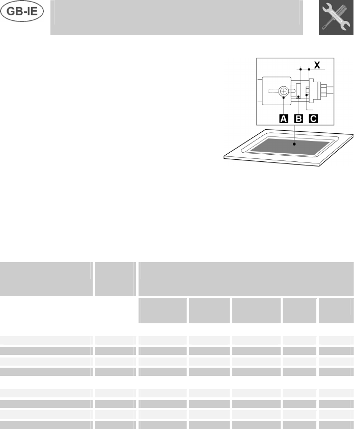
Loosen screw A and push air
regulator B to the bottom.
Witha7mmwrench,removenozzle
C and replace it with the proper one
(follow the instructions on the
reference tables for the type of gas
to be used).
The torque wrench setting of the
nozzle must not exceed 3Nm.
Regulate the air by sliding regulator
B until reaching distance “X” shown
in the table in paragraph “3.4
Regulation of primary air”.
Lock regulator B by tightening
screw A.
Burner
Rated
heating
capacity
(kW)
LPG – G30/G31 28/37 mbar
Nozzle
diameter
1/100 mm
By-pass
mm
1/100
Reduced
flowrate
(W)
Flowrate
g/h G30
Flowrate
g/h G31
Top with front controls:
Auxiliary 1.05 48 33 420 76 75
Semi rapid 1.65 62 33 420 120 118
Rapid 2.55 75 50 900 185 182
Ultrarapid 3.25 85 68 1500 236 232
Top with side controls:
Auxiliary 1.05 48 33 450 76 75
Semi rapid 1.65 62 33 450 120 118
Rapid 2.55 75 45 800 185 182
Ultrarapid 3.25 85 65 1500 236 232


