


Consult the designs in the front pages referenced in the text
by alphabet letters.
Closely follow the instructions set out in this manual
All responsibility, for any eventual inconveniences, dam-
ages or fires caused by not complying with the instruc-
tions in this manual, is declined.
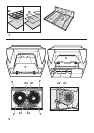
Suction Cooker hood Description - Fig. 1- various
models
A. Vapour collector
B. Suction grill
C. Controls
D. Light point
Use- Fig.1: The cooker hood is supplied with an upper air
outlet E with connection ring F; a discharge pipe G1 of the
same diameter as the connection ring (not supplied) is to be
mounted on the connection ring for discharging fumes
externally (Suction Version).
In cases where external fumes and vapour discharge is not
possible, the cooker hood may be used in the Filter
Version by simply mounting a carbon filter, and deflector
(G2-with two screws) in place of the discharge pipe on the
upper air outlet or directly in place of the connection ring (G3
with one screw), for discharging of fumes above the cabinet.
If necessary, a small tube trunk equivalent to the connection
ring is mounted in order to reach above the cabinet, the
deflector (if supplied) is then affixed to the hole cut out on the
top of the cabinet for the discharging of fumes. The models
without suction motor function only in the suction version
and must be connected to an external suction unit (not
supplied).
Installation: Do not tile, grout or silicone this appliance to
the wall. Surface mounting only.
Do not fix chimney flue to furniture or fly over shelves unless
the chimney flue can be easily removed, in case
maintenance is ever required. The cooker hood must be
positioned at a minimum distance to the cooktop of 65 cm
for electric top cookers and 70 cm for mixed or gas top
cookers. If the instructions for installation for the gas hob
specify a greater distance, this must be adhered to. The
cooker hood may be installed directly to the wall or between
hanging cabinets (see mounting diagram).
The vapour collector must be covered with an aesthetic
covering panel.
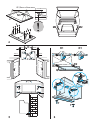
Affixing the aesthetic panel - Fig. 3, remove the suction
grill (B-Fig.1), depending on the model turn the lateral
handles and remove the grill by sliding towards the bottom
(H1-Fig.2) or pull the handles upwards and slide out the
suction grill (H2-H3-H4-Fig.2), remove the vapour collector
(freeing the locking releases I-Fig.3), apply the drill holes
diagram N3 on the rear of the aesthetic panel (Fig.4,J-the
arrow on the diagram should face the upper border of the
aesthetic panel), perform blind holes as indicated (K-Fig.4),
place the vapour collector over the aesthetic panel and affix
with 8 screws (Fig.4,L), remount the cover on the cooker
hood firstly in the upper track (Fig.4-M1), then in the lower
track (Fig.4-M2), where the cooker hood is provided with
revolving locking releases (Fig. 3) these should be turned
in the opposite direction of the release to avoid that the
vapour collector may be unintentionally released during
normal use of the cooker hood.
Affixing the cooker hood to side cabinets use the drill
holes diagram N2, position the diagram on the anterior
borders of the cabinet (right cabinet must remain visible
on the letter B of the drill holes diagram) (left cabinet must
remain visible on the letter C of the drill holes diagram) drill
the holes
IRRESPECTIVE OF THE THICKNESS OF THE
CABINET DOOR.
Where the side cabinet thickness is 16mm apply spacers
if supplied (Fig. 5,O) to the sides of the cooker hood
corresponding to the drill holes specified for the screws.
Fasten the cooker hood with 4 screws (Fig. 5,P), place
the connection ring and discharge pipe (or deflector if
supplied) to the cooker hood outlet (see Use section),
mount the lower bracket (Fig. 5,Q) to the cooker hood with
two screws and plastic washers (Fig. 6,T).
Affixing the cooker hood to the wall use the drill holes
diagram N1, drill as indicated, insert two hooks in the upper
drill holes (Fig.6,R1) and two dowels in the lower drill holes
(Fig.6,R2), fasten the lower bracket to the wall with two
screws (Fig.6,Q), hang the cooker hood on the wall,
regulate the position of the cooker hood (Fig.6 - screws S1
for vertical regulation, screws S2 for depth regulation),
place connection ring and discharge pipe (or deflector if
supplied) to the cooker hood outlet (see Use section),
fasten the cooker hood to the lower bracket (Fig.6,Q) with
two screws and plastic washers (Fig. 6,T).
Access to the screws that secure the lower bracket may
be through the drill holes located inside the cooker hood
(Fig.6,U).
Electrical connection: The electrical tension must
correspond to the tension noted on the label placed inside
the cooker hood. Connect the electrical plug, where
provided, to the an easily accessible outlet in conformity
with local standards in force. Where an electrical plug is not
provided (for direct connection to electrical network) place
a standards approved bipolar switch with an aperture
distance of not less than 3mm (accessible) from the
contacts.
Caution: This appliance is designed to be operated by
adults. Children should not be allowed to tamper with the
controls or play with the appliance.
Do not use the cooker hood where the grill is not correctly
fixed! The suctioned air must not be conveyed in the same
channel used for fumes discharged by appliances powered
by other than electricity. The environment must always
be adequately aerated when the cooker hood and other
appliances powered by other than electricity are used at
the same time. Flambé cooking with a cooker hood is
prohibited. The use of a free flame is damaging to the filters
and may cause fire accidents, therefore free flame cooking
must be avoided. Frying of foods must be kept under close
control in order to avoid overheated oil catching fire. Carry
out fumes discharging in accordance with the regulations
in force by local laws for safety and technical restrictions.