


Instructions for the installer
6
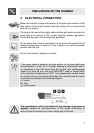
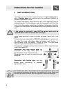
2 POSITIONING OF THE HOB
The following operation requires building and/or carpentry work so mus
t
be carried out by a competent tradesman.
Installation can be carried out on various materials such as masonry,
metal, solid wood or plastic laminated wood as long as they are hea
t
resistant (T 90°C).
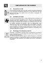
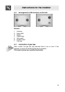
2.1 Attachment to support structure
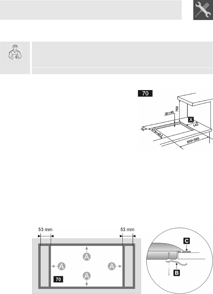
Create an opening with the dimensions
shown in the figure in the top surface of
the counter, keeping a minimum
distance of 50 mm from the rear border.
This appliance can be mounted against
walls higher than the work surface on
condition that a certain distance “X” be
kept between the appliance and the wall
as shown in the figure so as to avoid
damage from overheating.
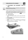
Make sure there is a minimum of 750 mm between the hot plate flames
and any shelf that may be installed directly above them. Accurately
position the gasket provided all around the outer edge of the hole in the
top surface as shown in the figures below, pressing it down so as to
make it adhere properly. Refer to the dimensions shown in the diagram,
bearing in mind that the sides A must be flush with the hole. Fix the hob
to the unit using the brackets B provided.
Carefully trim any excess from border C of the gasket. The distances in
the following drawing refer to the hole on the inner side of the gasket.