


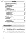
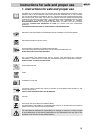
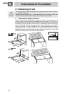
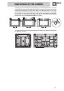
Instructions for the installer
26
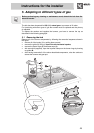
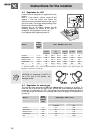
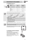
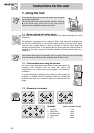
5.2 Regulation for LPG
Loosen screw C and push air regulator D to the
bottom.
With a 7 mm wrench, remove nozzle E and
replace it with the proper one (follow the
instructions on the reference tables for the type of
gas to be used). The torque wrench setting of the
nozzle must not exceed 3 Nm.
Regulate the air by sliding regulator D until
reaching distance “X” shown in the table in
paragraph “5.4 Regulation of primary air ”.
Lock regulator D by tightening screw C.
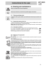
Burner
Rated
heating
capacity
(kW)
LPG – G30/G31 28/37 mbar
Nozzle
diameter
1/100 mm
By-pass
mm
1/100
Reduced
flowrate
(W)
Flowrate
g/h G30
Flowrate
g/h G31
Auxiliary 1.0 48 30(**) 30 (*) 450 73 72
Semi rapid 1.6 62 30(**) 33 (*) 500 116 114
Medium rapid 2.3 75 40(**) 40 (*) 700 167 164
Large rapid 3.0 82 40(**) 45 (*) 800 218 215
A 76
UR
B
3.6
48
48 (**) 50 (*) 1000 261 257
*/**: diameters marked * and ** must be fitted respectively on valves marked * and **shown inpoint “5.6
Regulation of minimum for natural gas”.
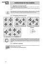
CAUTION: for references A and B on
the lh UR and rh UR burners, see
drawings at side.
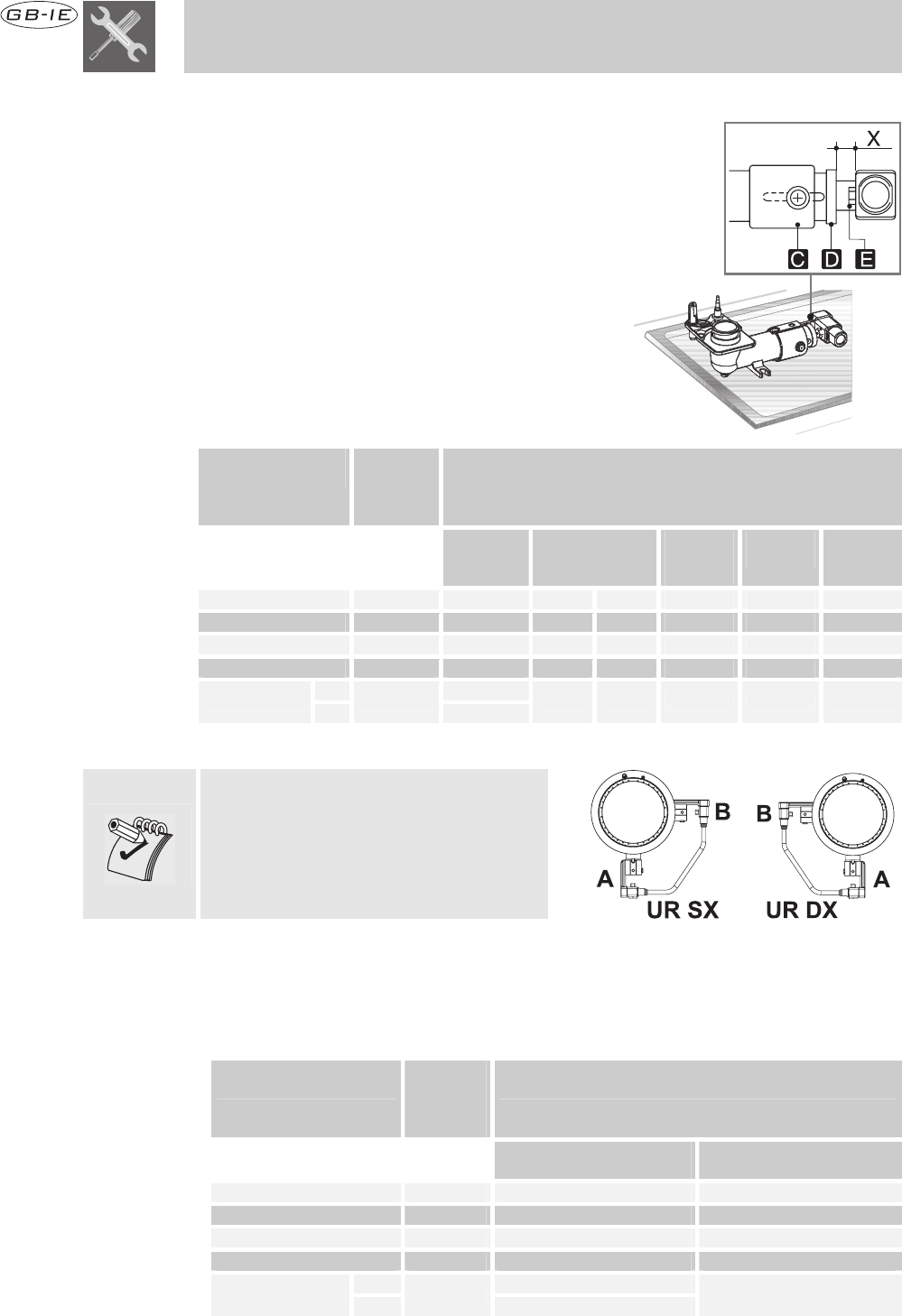
5.3 Regulation for natural gas
The hob has been inspected for G20 (2H) natural gas at a pressure of 20 mbar. To
allow the unit to work with this type of gas, perform the same operations described in
paragraph “5.2 Regulation for LPG ”, but choose the nozzles and regulate the primary
air for natural gas, as shown in the following table and in paragraph “5.4 Regulation of
primary air ”.
Burner
Rated
heating
capacity
(kW)
Natural gas – G20 20 mbar
Nozzle diameter
1/100 mm
Reduced flowrate
(W)
Auxiliary 1.0 73 400
Semi rapid 1.65 92 500
Medium rapid 2.3 110 700
Large rapid 3.0 126 800
A 115
UR
B
3.6
73
1000