


7
SERVICING
Always disconnect the appliance from the
electricity main before proceeding with any
servicing operation.
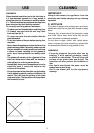
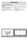
8) REPLACING THE ELECTRICAL
COMPONENTS
For access to the various parts, remove the hotplate
from the top of the cabinet. Then overturn it, unscrew
screw “Z” and remove under part. (see fig. 8).
After these actions is possible to work on the
plates, commutators, clamps and input cable.
N.B. In case of substitution of the input cable,
the installer must keep the “earth” conductor
longer than “live” ones, and must respect the
cautions in paragraph “Electrical connection”.
To reassemble the appliance repeat the inverse
process.
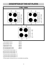
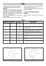
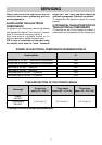
9) TECHNICAL CHARACTERISTICS OF
THE ELECTRICAL COMPONENTS
To facilitate the job of the installer we present a
scheme with the characteristics of the components.
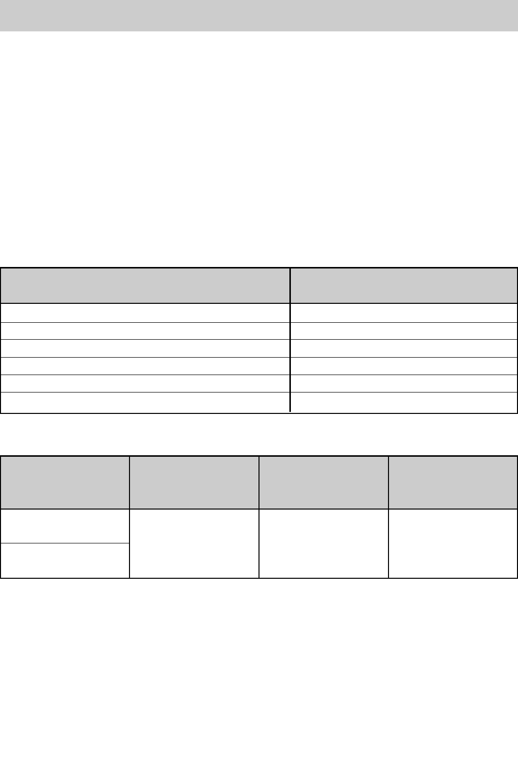
POWER OF ELECTRICAL COMPONENTS DENOMINATIONS W
Normal plate Ø 145 mm – 7 positions with the protector 1000
Normal plate Ø 180 mm – 7 positions with the protector 1500
Rapid plate Ø 145 mm – 7 positions 1500
Rapid plate Ø 180 mm – 7 positions 2000
Thermostat plate Ø 145 mm – 12 positions 1500
Thermostat plate Ø 180 mm – 12 positions 2000
Denominations W
TYPE AND SECTION OF THE POWER CABLES
Rubber
H05 RR-F
Polycroropene 3 X 2.5 mm
2
(*) 5 X 1.5 mm
2
(*) 4 X 1.5 mm
2
(*)
H05 RN-F
Single phase Three phase Three phase
Cable type
power 230 - 240 V ~ power 400 - 415 V 3N~ power 400 - 415 V 2N~
(*) keeping in mind the contemporaneousness factor