


Instructions for the installer
29
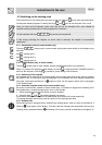
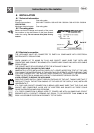
8.4 Positioning of the hob
The following operation requires building and/or carpentry work so must be carried out by a
competent tradesman.
Installation can be carried out on various materials such as masonry, metal, solid wood or
plastic laminated wood as long as they are heat resistant (T 90°C).
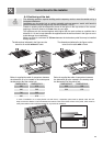
Create an opening with the dimensions shown in the figure in the top surface of the counter,
keeping a minimum distance of 50 mm from the rear edge.
This appliance can be mounted against walls higher than the work surface on condition that a
distance of 110 mm be kept between the appliance and the wall as shown in the figure so as to
avoid damage from overheating.
Make sure there is a minimum of 750 mm between the hob and any shelf that may be installed
directly above it.
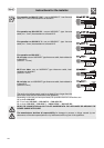
The dimensions indicated in the figure are the
same for all models without a frame.
The dimensions indicated in the figure are the
same for all models with a frame.
Below is supplied the table of comparison between
the dimension Y to be created in the worktop and
the dimension X of the cooker hob.
Below is supplied the table of comparison between
the dimension K to be created in the worktop and
the dimension Z of the cooker hob.
DIMENSION X DIMENSION Y DIMENSION Z DIMENSION K
300 270 600 560
600 565 900 879
700 565
900 878
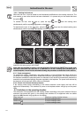
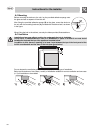
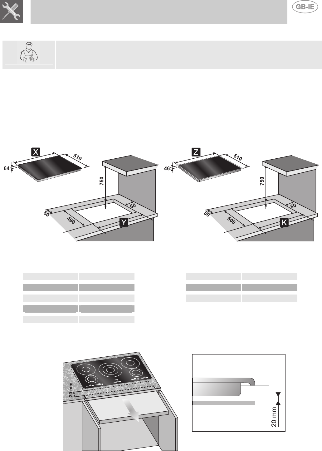
In case of installation on an empty kitchen unit with doors, a separation panel must be placed under the hob.
Keep a minimum distance of 20 mm between the bottom of the hob and the surface of the panel, which must be
easily extractable to allow sufficient access for any technical assistance.