


ADJUSTMENTS MODEL 300 RESTAURANT RANGES
ADJUSTMENTS
! WARNING
ADJUSTMENTS AND SERVICE WORK MAY BE PERFORMED ONLY BY A QUALIFIED
TECHNICIAN WHO IS EXPERIENCED IN, AND KNOWLEDGEABLE WITH, THE OPERATION OF
COMMERCIAL COOKING EQUIPMENT. HOWEVER, TO ASSURE YOUR CONFIDENCE,
CONTACT YOUR AUTHORIZED SERVICE AGENCY FOR RELIABLE SERVICE, DEPENDABLE
ADVICE OR OTHER ASSISTANCE, AND FOR GENUINE FACTORY PARTS.
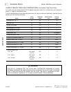
In case of problems in operation at initial installation, check type of gas and manifold pressure and compare
with information listed on the serial plate.
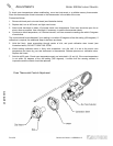
GAS PRESSURE REGULATOR
The pressure regulator is factory set at 4" W.C. for natural gas and 10" W.C. for propane gas. To check the
manifold pressure:
1. Turn all thermostats and burner valves to “OFF” position.
2. Turn main gas valve to entire unit off.
3. Remove valve panels and locate 1/8" plug in manifold.
4. Remove plug and install a fitting appropriate to connect a manometer.
5. Turn on main gas to unit and light pilots.
6. Turn all burners and ovens to full “ON” position and read manometer.
7. If manometer does not read 4" W.C. for natural gas, or 10" W.C. for propane gas, adjust regulator (if gas
pressure is O.K. go to Step 10).
8. Remove cap from top of regulator.
9. With a screwdriver rotate regulator adjustment screw “clockwise” to increase, or “counterclockwise” to
decrease, pressure until manometer shows correct reading.
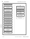
ADJUSTMENTS
10. Repeat steps 1 and 2.
11. Remove manometer fitting and replace plug in manifold.
12. Repeat step 5.
13. Replace valve panels.
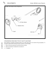
TOP PILOTS: NON-AERATED (YELLOW-TIPPED FLAME) TYPE
These are located under fry-tops, hot-tops, broiler-griddles and on the flash tube system of open top grate
burners.
Outage is often caused by an unstable flame due to over-adjustment to the point where the flame is leaving
its port, or “blowing off.”
Often, in an effort to improve ignition, the pilots are increased too much and result in this unstable condition.
These pilots are adjusted by inserting the blade of a screwdriver into the slot on the small valve, located on
the manifold. The maximum flame size is approximately 3/4" with a slight yellow tip. The first indication of
over-adjustment is evident when the yellow tip begins to stream into black streaks and generate carbon.
Continued over-adjustment leads to the unstable lifting and blowing condition.
PAGE 24 OPERATOR’S MANUAL 1182298 REV 3