


INSTALLATION GFS SERIES TUBE FRYERS
PAGE 10 OPERATOR’S MANUAL 1182026 REV 2
INSTALLATION
Step 5: Gas Connection
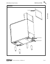
A 3/4" male NPT line for the gas connection is located near the lower left rear corner of the fryer (see
illustration on page 7). The serial plate (located inside the front door of the fryer) indicates the type of gas the
unit is equipped to burn (natural gas or propane). The fryer should be connected ONLY to the type of gas for
which it is equipped.
A millivoltage circuit diagram is located inside the front door of the fryer.
All Southbend equipment is adjusted at the factory; however, pilot height should be checked at installation
and adjusted, if necessary (see page 22).
For orifice sizes and pressure regulator settings, see the chart on page 5. If the fryer is being installed at over
2,000 feet altitude and that information was not specified when ordered, contact the appropriate authorized
Southbend Service Representative or the Southbend Service Department. Failure to install with proper
orifice sizing will result in poor performance and may void the warranty.
If applicable, the vent line from the gas appliance pressure regulator shall be installed to the outdoors in
accordance with local codes or, in the absence of local codes, with the National Fuel Gas Code, ANSI
Z223.1, Natural Gas Installation Code, CAN/CGA-B149.1, or the Propane Installation Code, CAN/CGA-
B149.2, as applicable.
An adequate gas supply is imperative. Undersized or low pressure lines will restrict the volume of gas
necessary for satisfactory performance. A combination gas valve and pressure regulator, which is provided
with each unit, is set to maintain a 4" W.C. manifold pressure for natural gas or 10.0" W.C. manifold pressure
for propane gas. However, to maintain these conditions the pressure on the supply line, when all units are
operating simultaneously, should not drop below 7" W.C. for natural gas or 11" W.C. for propane gas.
Fluctuations of more than 25% on natural gas or 10% on propane gas will create problems and affect burner
operating characteristics. A 1/8" tap to measure the manifold pressure is located on the combination gas
valve, which is on the burner manifold located directly below the burners inside the cabinet.
Purge the supply line to clean out dust, dirt, or other foreign matter before connecting the line to the unit.
It is recommended that an individual manual shutoff valve be installed in the gas supply line to the unit.
Use pipe joint compound that is suitable for use with both natural and LP gas on all threaded connections.
! CAUTION
ALL PIPE JOINTS AND CONNECTIONS MUST BE TESTED THOROUGHLY FOR GAS LEAKS.
USE ONLY SOAPY WATER FOR TESTING ON ALL GASES. NEVER USE AN OPEN FLAME TO
CHECK FOR GAS LEAKS. ALL CONNECTIONS MUST BE CHECKED FOR LEAKS AFTER THE
UNIT HAS BEEN PUT INTO OPERATION. TEST PRESSURE SHOULD NOT EXCEED 14" W.C.
! CAUTION
THIS APPLIANCE AND ITS INDIVIDUAL COMBINATION GAS VALVE MUST BE DISCONNECTED
FROM THE GAS SUPPLY PIPING SYSTEM DURING ANY PRESSURE TESTING OF THAT
SYSTEM AT TEST PRESSURES IN EXCESS OF 1/2 PSIG (3.45 kPa).
The appliance must be isolated from the gas supply piping system by closing its individual manual
shutoff valve during any pressure testing of the gas supply piping system at test pressures equal to or
less than 1/2 psi (3.45 kPa).
Connect the gas supply directly to the 3/4" male NPT connector located near the lower left rear corner of the
fryer. When tightening the supply pipe, be sure to hold the mating connector extending from the unit securely
with a wrench. This will prevent any damage or distortion to the internal piping and controls of the unit.
After connecting the gas supply, check again that the fryer is level. Use a long spirit level four ways; across
the front and rear of the frypot, and along each edge.