


INSTALLATION HEAVY DUTY COUNTERLINE
PAGE 10 OWNER’S MANUAL 1192662
INSTALLATION
Step 4: Connect Gas Supply
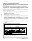
The serial plate is located interior side of the control panel (see Figure 1 on page 3). It indicates the type of
gas the appliance is equipped to burn. All Southbend equipment is adjusted at the factory. Check type of
gas on serial plate. This appliance should be connected ONLY to the type of gas for which it is equipped.
If the appliance is being installed at over 2,000 feet altitude and that information was not specified when
ordered, contact the appropriate authorized Southbend Service Representative or the Southbend Service
Department. Failure to install with proper orifice sizing will result in poor performance and may void the
warranty.
These models are design-certified for operation on natural or propane gases. For natural gas, the
convertible regulator shipped with the appliance is set to deliver a 4" W.C. pressure to the manifold. For
propane gas, it is set to deliver 10" W.C.
An adequate gas supply is imperative. Undersized or low pressure lines will restrict the volume of gas
required for satisfactory performance. Fluctuations of more than 25% on natural gas or 10% on propane
gas will create problems and affect burner operating characteristics. A 1/8" pressure tap is located on the
manifold to measure pressure.
Purge the supply line to clean out dust, dirt, or other foreign matter before
connecting the line to the
appliance.
Use pipe joint compound that is suitable for use with LP gas on all threaded connections.
! CAUTION
ALL PIPE JOINTS AND CONNECTIONS MUST BE TESTED THOROUGHLY FOR GAS LEAKS.
USE ONLY SOAPY WATER FOR TESTING ON ALL GASES. NEVER USE AN OPEN FLAME TO
CHECK FOR GAS LEAKS. ALL CONNECTIONS MUST BE CHECKED FOR LEAKS AFTER THE
APPLIANCE HAS BEEN PUT INTO OPERATION. TEST PRESSURE SHOULD NOT EXCEED 14"
W.C.
To connect the gas supply, do the following:
1. Check that the gas supply to the piping that will be connected to the appliance is shut off.
2. Check that the manual shut-off valve inside the front panel door of the appliance is closed (60" and 72"
models have two shut-off valves).
3. Check that all control knobs on the appliance are turned “OFF.”
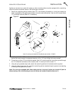
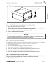
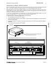
4. Attach the pressure regulator shipped with the appliance to the 3/4" NPT gas inlet connector located on
the rear of the appliance (see Figure 4 below). Be sure that the regulator is connected so that the gas
flow is in the
same direction as the arrow on the bottom of the regulator.
5. Connect the vent line from the pressure regulator to the outdoors in accordance with local codes or, in
the absence of local codes, with the National Fuel Gas Code, ANSI Z223.1, Natural Gas Installation
Code, CAN/CGA-B149.1, or the Propane Installation Code, CAN/CGA-B149.2, as applicable.
6. Connect the gas inlet of the pressure regulator to the building’s supply system. No segment of the gas
supply connection to the appliance should be smaller than 3/4" NPT. Standard pipe fittings are
required.
7. Turn on gas supply.
8. Check for leaks using soapy water.