


INSTALLATION PLATINUM SERIES SECTIONAL RANGE
PAGE 30 OF 80 INSTALL & OPERATIONS MANUAL 1185836 REV 3 (07/06)
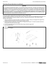
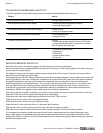
4. Attach each wall shield to the back of the corresponding flue riser using the provided #10 sheet metal screws.
5. Connect the top side edges of adjoining flue risers using the provided small plates and screws.
6. If tubed shelves were installed, place the tubes in place in the shelf brackets.
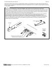
7. If sloped enclosures were ordered (for flue-mounted salamander broilers and/or cheese melters), install them at
this time.
STEP 6: CONNECT ELECTRICITY (FOR SECTIONS WITH OVEN-BASES)
A wiring diagram is located behind the kick panel of the oven-base ranges. Be sure that the input voltage and phase
match the requirements shown on the serial plate.
Oven-base ranges ordered with a 115V, 60Hz, single-phase electrical rating are factory-supplied with a three-wire
cord with a three-prong plug that fits any standard three-prong grounded receptacle. Each standard oven requires a
15 ampere supply, while each convection oven requires a 20 ampere supply.
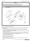
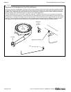
Oven-base ranges ordered with a 208/236V, 60Hz, single- or three-phase electrical rating are factory-equipped with
a two-pole terminal block located behind cover plate located on the rear of the unit. To connect the supply wires,
remove the cover plate. Route the supply wires and the grounding wire through the strain relief fitting to the terminal
block. Insert the supply wires, one each, into the two poles of the terminal block and tighten the screws. Insert the
ground wire into the grounding lug and tighten the screw. Re-attach the cover plate.
Three phase units are wired as above, using only two supply wires. The third wire is not used and must be properly
terminated.
All units are shipped wired as specified by factory order. Conversion between single-phase and three-phase can be
accomplished by referring to phase loading and line amperes chart on the wiring diagram for wire size and ampere
requirements.
STEP 7: CONNECT GAS SUPPLY
If the sectional range is being installed at over 2,000 feet altitude and that information was not specified when
ordered, contact the appropriate authorized Southbend Service Representative or the Southbend Service
Department. Failure to install with proper orifice sizing will result in poor performance and may void the warranty.
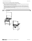
The sectional range is design-certified for operation on natural or propane gases. The sectional range is shipped
configured and adjusted for the type of gas specified by the purchaser, which is indicated on the serial plate (see
Figure 1 on page 3). Connect the sectional range ONLY to the type of gas for which it is configured and adjusted.
Minimum supply pressure is 7" W.C. for natural gas, 11" W.C. for propane. An external pressure regulator and shut off
valve are provided. If using a flexible-hose gas connection, the I.D. of the hose must not be smaller than the
connector on the sectional range, and must comply with ANSI Z21.69. Provide an adequate means of restraint to
prevent undue strain on the gas connection.
If applicable, the vent line from the gas pressure regulator shall be installed to the outdoors in accordance with local
codes, or in the absence of local codes, with the National Fuel Gas Code, ANSI Z223.1, Natural Gas Installation
Code, CAN/CGA-B149.1, or the Propane Installation Code CAN/CGA-B149.2, as applicable.
An adequate gas supply is imperative. Undersized or low pressure lines will restrict the volume of gas required for
satisfactory performance. Fluctuations of more than 25% on natural gas or 10% on propane gas will create problems
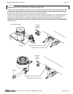
and affect burner operating characteristics. A 1/8" pressure tap is located on the manifold to measure the manifold
pressure. The supply line to the sectional range should be no smaller than the inside diameter of the pipe on the
sectional range to which it is connected.
CAUTION
ALL PIPE JOINTS AND CONNECTIONS MUST BE TESTED THOROUGHLY FOR GAS LEAKS. USE ONLY
SOAPY WATER FOR TESTING ON ALL GASES. NEVER USE AN OPEN FLAME TO CHECK FOR GAS LEAKS.
ALL CONNECTIONS MUST BE CHECKED FOR LEAKS AFTER THE APPLIANCE HAS BEEN PUT INTO
OPERATION. TEST PRESSURE SHOULD NOT EXCEED 14" W.C.
Do the following to connect the gas supply:
1. Check that all control knobs on the sectional range are in the OFF position.
2. Purge the gas supply line to clean out dust, dirt, or other foreign matter before connecting the line to the sectional
range.