


LIST OF ILLUSTRATIONS
Figure Title Page
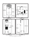
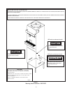
1 Model E157 - Front......................................................................................................................... 2
2 Model E157 - Side.......................................................................................................................... 2
3 Model E257/F257 - Front ................................................................................................................ 2
4 Model E257/F257 - Side ................................................................................................................. 2
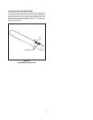
5 Adjustable Leg ............................................................................................................................... 3
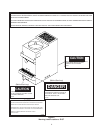
6 Warning Label Locations - E157 ..................................................................................................... 4
7 Warning Label Locations - E257/F257 ............................................................................................ 5
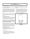
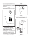
8 Space & Ventilation Requirements ................................................................................................. 6
9 Electrical Plug ................................................................................................................................ 6
10 Installing Sani-tray and Cover ......................................................................................................... 6
11 Adjusting Cup Dispensers .............................................................................................................. 7
12 Operating Controls ......................................................................................................................... 9
13 Removing Sani-tray and Cover ........................................................................................................ 11
14 Draining Product............................................................................................................................. 11
15 Removing Spigot Assembly............................................................................................................ 12
16 Removing Spigot O-Ring from Spigot Body ..................................................................................... 12
17 Cut-away View of Spigot Assembly ................................................................................................ 12
18 Removing Drive Cap and O-Ring ..................................................................................................... 13
19 Removing Sealer Ring .................................................................................................................... 13
20 Removing Agitator Assembly and Lower Bushing ........................................................................... 13
21 Removing Divider Plate from Agitator Fingers ................................................................................. 14
22 Removing Drive Shaft ...................................................................................................................... 14
23 Exploded View of Divider Plate and Agitator Assembly ................................................................... 14
24 Lubricating Drive Shaft .................................................................................................................... 15
25 Installing Divider Plate and Agitator Assembly ................................................................................16
26 Proper Installation of Sealer Ring .................................................................................................... 16
27 Correct and Incorrect Alignment of Vertical Center Post Guide Hole ............................................... 16
28 External Parts To Be Cleaned ........................................................................................................ 19