


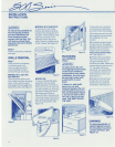
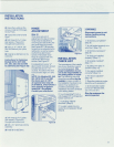
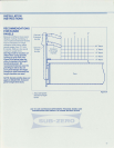

INSTALLATION
INSTRUCTIONS
2) Using the Loctite on the
screws, install
all
3 Chicago
Screw Posts.
3) Inspect the units for level
again.
4) Drill three
(3)
3h6" holes
(per specs in Figure 24)
through both outer trims.
5) Using a '/a" drill bit, drill
into the cabinetry for a pilot
hole.
6) Install
all
six
(6)
Sems to the
cabinetry.
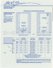
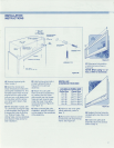
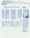
Instructions for fastening
Models
501R, 501F, 550,
511,561,532,542
and
590
to cabinetry (see Figure 25):
I
17'1/1"
J
I
17'/it"
L
""t
77'/8"
1) Drill three (3) 3h
6"
holes
(per specs in Figure 25)
through both outer trims.
2) Drill a '/a" pilot hole into the
cabinetry.
3) Install
all
six (6) Sems.
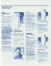
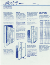
HINGE
ADJUSTMENT
Step
16
If
the doors are out of
adjustment, the
top
or bottom
hinge
may
be
adjusted
by
removing
and
discarding the
two
small shipping screws.
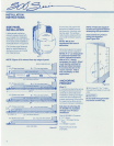
See Figure 26. The top
door
hingescan
be
adjusted left to
right and in or out by loosen-
ing the three allen head
screws. The bottom
door
hinge
is
equipped
with
two
adjustment allen hbad
screws. See Figure 27.
For adjustment, use a
'/a"
allen wrench to loosen screws
(models 550 and
511
ex-
cluded). This allows the
door
to move left to right or in and
out.
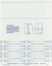
NOTE: On Models 532, 542,
561, 501
R,
501F
and
590
the doors open to 130
0
•
An optional doorstop kit
(4-20-089-0), which allows a
dooropening
of
approxi-
mately
90
0
is
available.
Contact yourdistributor.
Figure
26
Figure
27
INSTALLATION
CHECKLIST
The importance of the installa-
tion of your Sub-Zero cannot
be
overemphasized. The
proper
installation
of
your
unit is the responsibility
of
the selling
dealer
or
instal-
ler,
The following check list
should
be
completed by the
installerto insure no part of
the installation has been over-
looked.
Any
questions or
problems pertaining to the
installation should
be
directed
to the selling dealer.
o
Is
unit operating?
If
not, is
unit
plugged
in? Is refrigeratorl
freezer control on?
o
Is
packing material
removed? (Step
6)
o Is water supply line con-
nected to compression fitting?
(Step
8)
IAWARNINGI
Disconnect
power
to unit
before checking wiring
connections.
o Is blocking completed?
(Step
8)
o Is unit leveled properly on a
solid floor? (Step 10)
o Is blocking necessary?
(Step
8)
o Is drain pan installed
properly? (Step 11)
o Is toe plate installed?
(Step 11)
o Is grille screw
back
in
position? (Step 12)
o Are panels installed
correctly? (Step 14)
o Are
doors
adjusted?
(Step 16)
o Does the customer under-
stand the unit's operation?
o
Is
the icemaker switch
turned on? (Models 590,
532, 542 and 561).
Give the customer the
warrantypacket.
9