


page 9
3.0 OPERATION OF VACUUM GAUGE
3.13.1
3.13.1
3.1
PP
PP
P
oo
oo
o
ww
ww
w
erer
erer
er
ing of ing of
ing of ing of
ing of
VV
VV
V
acuum Gaugeacuum Gauge
acuum Gaugeacuum Gauge
acuum Gauge
Plug the 8 ft. power cable into a single phase 115 VAC (DNV-33D) or 230 VAC (ENDV-
33D)line. A line frequency of either 50 or 60 Hz is satisfactory. Allow 30-40 minutes for warm-
up.
Plug the gauge tube cable onto the gauge tube. When the tube is exposed to a pressure greater
than1000 mTorr, the analog output will be over 2 volts, and the display will read “1”.
The relay will energize when the pressure is below the trip points. “Normal” relay position is de-
energized (ATM pressure side of set point.)
3.23.2
3.23.2
3.2
Switch PSwitch P
Switch PSwitch P
Switch P
ositionosition
ositionosition
osition
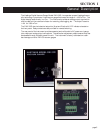
“OPR” Normal operating position. Display reads pressure. Output on back panel reads 0-1
volt.
“SET A; SET B” Displays the trip point of the appropriate relay. If the pressure is below the trip
point the relay is energized and the LED will be lit. The trip points can be set from 0-950 mTorr.
The relay trip points are set by adjusting the appropriate pot located on the front panel.
“CAL” Used when zeroing the vacuum gauge tube at hard vacuum. Adjust the Cal pot on the
rear panel for 000 on the display.
“Test” A voltage is injected into the 2
nd
stage AMP so that the GAIN of the gauge can be set on
the average curve. Adjust ‘GAIN’ pot on rear panel for “400” on the display. NOTE: The
signal output will change when the switch is put in this position and the set points may trip. See
section 4.2.1 Reference Check.
4.0 CALIBRATION AND TROUBLESHOOTING GUIDE
All Hastings vacuum gauges and tubes have been carefully checked and calibrated at the factory
before shipment. If a calibration check is desired the methods in the following sections may
prove helpful.
4.14.1
4.14.1
4.1
Check of Check of
Check of Check of
Check of
TT
TT
T
ube ube
ube ube
ube
AccuracAccurac
AccuracAccurac
Accurac
yy
yy
y
The simplest and quickest method of checking the operation and calibration of power supply/
display and gauge tube is to keep a new, clean gauge tube on hand as a “standard”. To check
operation, install both of the gauge tubes together in the same clean, dry vacuum system, and
pump until a steady pressure is obtained. Plug the gauge onto both tubes alternately and check
reading. Be sure to allow time for readings to settle. If the tube reads a considerably higher
pressure than the tube being used as a standard, a calibration shift in the old tube has occured.
This is most likely resulting from tube contamination. The tube calibration can possibley be
restored by gently rinsing the interior of the tube with a solvent such as trichlorethylene. After
cleaning, thoroughly dry the tube and degas it before reinstallation into a vacuum system. This
is done to avoid system contamination by the solvent. If calibration cannot be restored by this
precedure, replace the old tube with a new gauge tube.
CAUTION: Do not attempt to measure the resistance of the gauge tube element while it is
under vacuum. Some ohmmeters apply measuring voltages sufficient to burn out the thermo-
pile while under vacuum. The resistance of the gauge tube can be measured safely at atmo-
spheric pressure. This measurement is made between pins 3, 5 and 7 counting clockwise from
the key looking at the base of the gauge tube. A measuring device such as the Triple Model 630
Test Set with ohms switch on the “X10” range, is suitable for this purpose.