


Page 5
Fig. 5
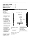
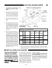
CABINET AND COUNTERTOP DIMENSIONS
3" Min. to Wall
3" Deep
from Top
of Counter
21-3/4"
1" Min. to Wall
"F"
"B"
"E"
3" Min. to Wall
3" Min. to Wall
1" Min.
1/8" Min. Clearance
from Cooktop Edge
to Start of Radius
COOKTOP
MODELS
DIM.
COOKTOP
WIDTH “B”
NEW*
INSTALLA-
TION OVER
CT130
GGS30,
GGN30,
26-1/2" min.
29-7/8" max.
30-3/4"
18-5/16" min.
20-15/16" max.
29-3/4"29-3/4"
20"
20"
SGS30 &
SGN30
GGS36/365,
GGN36/365,
SGS36G &
SGN36G
E
33" min.
35-1/8 max.
33-1/2"
35"
35"
F
18-5/16" min.
20-15/16" max.
20"
20"
19"
19"
27"
COUNTERTOP CUT-OUT DIMENSIONS
OVEN
SOLID**
SURFACE
MATERIAL
36"
F
E
NEW
INSTALLATION
EXCEPT
OVER CT130
OVEN
REPLACEMENT
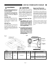
STEP FIVE: INSTALL THE COOKTOP
APPLY TAPE AND SECURE
COOKTOP TO COUNTER
A foam tape is provided to seal
the cooktop edges to the counter-
top, shown in Fig. 6. Apply tape to
the cooktop glass on the perimeter
prior to installing the cooktop.
Position the tape to the glass on
Models GGS & GGN and to the
burner box on Models SGS & SGN
(as shown).
The cooktop may be secured to
the countertop using hold-down
brackets provided. Attach
clamps to the burner box using
washer andscrews provided prior
to inserting cooktop into the cut-
out. Insert cooktop into cutout.
Adjust hold down brackets to
desired position and tighten
screws to burner box. Insert
clamping screw into clamp and
secure cooktop to counter top,
see Fig. 6 on Page 6.
Counter tops made from SOLID SUR-
FACING MATERIALS, such as Surell™
and Corian
®
, require special cut-out
preparation and installation procedures.
Follow the manufacturers guidelines in
preparing the cut-out to the dimensions
noted in Fig. 5, above.
Continued on Page 6
* Cooktops installed over CT130 ovens require larger cutouts (see Fig. 5).
** Solid surfacing material countertops such as Surell
™
and Corian
®
require
larger cutouts and special installation specified in cooktop securement
section, (see Step 5).
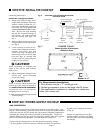
1. See Cabinet Considerations
under
Step One: Before You Begin,
page 3.
2. Instructions are based on Stan-
dard American cabinets 36" high
x 24" deep.
If nonstandard cabi-
nets are used care should be taken
to alter dimensions accordingly.
3.
All cutout dimensions given in
figure 5 have to be precisely fol-
lowed.
4. Plan the installation of the unit so
that the power cord, gas shut-off
valve and gas pressure regulator
are accessible from the front of
cabinet. If a drawer is installed,
directly under the cooktop, its
depth should be no greater than
15 inches.
5. This unit has been Design Certi-
fied for installation in countertop
near adjacent walls and project-
ing surfaces constructed of com-
bustible materials. The minimum
horizontal distance from the back
edge of the cooktop to adjacent
vertical combustible wall, and
minimum horizontal distance
from front edge of cooktop to front
side of countertop is 1 inch. The
minimum horizontal distance
from the sides of the cooktop to
the adjacent vertical combustible
walls are as follows: left and right
side walls is 3 inches and to the
rear wall is 1 inch.
STEP FOUR: PREPARE CABINET