


5
P arts In cluded with your Hood
t Hood Canopy Assembly with blower already
installed
t Grease lters
t Drip tray for each lter.
t Use & Care / Installation Instructions
t Fittings bag with:
t Drip trays holding brakets + plastic wahers and
knobs
4 Washers
6 Drywall anchors
2 Hooks with regulating screws
6 Screws 5X35
4 Screws for transition
t 1 Transition withback draft damper
Op tion al accessory
Duct covers
Ductless recirculation kit available only for HMWB30,
HMWB36 model..
Parts Not Included with your
Hood
t Duct Tape
t 1/2" Conduit
t Wire Nuts
t Round Duct.
t Wiring clamp
t
CAUTION! Lamps are not supplied, use
ONLY 120 Volt, 50 Watt (maximum) 50°
halogen light made o r a GU10 base,
suitable for use i n open luminarie .
t 4 #10 pan head wood screws for installation on
a bottom of a cabinet
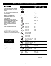
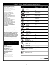
Tools required
Flat blade and Phillips screwdrivers
Pencil and tape measure
Metal snips (in some applications)
Electric drill
Saw (saber or keyhole)
Pliers
Level
Caulking
Flashlight
Wire s
tripper
Safety glasses
Gloves
Step ladder
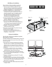
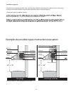
INSTALLING THE HOOD
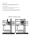
t For the most ecient air flow exhaust, use a
straight run or as few elbows as possible.
CAU TIO N: Vent unit to outside of
building, only.
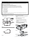
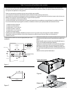
t Two people are necessaryfor installation.
On average 2 hours are necessary to complete
installation (without considering cut to be done
on wall and or on cabinet, installation of ducts ,
conduit and electrical connections to the mains) .
installation steps:
11 installation steps are required for both
installation methods
Wall mount installation steps or in alternative
Cabinet installation
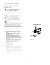
t The hood is tted with Screws and Drywall
Anchors suitable for most surfaces, consult a
Qualied Installer, check if they perfectly fit with
your cabinet/wall.
t Do not use ex ducting.
t COLD WEATHER installations should have an
additional backdraft damper installed to
minimize backward cold air ow and a
nonmetallic thermal break to minimize
conduction of outside temperatures as part of
the ductwork. The damper should be on the
cold air side of the thermal break.
The break should be as close as possible to
where the ducting enters the heated portion of
the house.
t Make u
p
air: Local building codes may require
the use of Make-Up Air Systems when using
Ducted Ventilation Systems greater than
specied CFM of air movement.
The specied CFM varies from location to location.
Consult your HVAC professional for specic
requirements in your area.
t
3 prong plug