English 13
Automatic Re-Ignition
If any one or more burners blow out, the electronic igniter
automatically activates to re-light the flame. Do not touch
the burners when the igniters are active.
Important:
• For proper combustion do not use the cooktop without
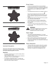
the burner grates in place.
• There is a slight sound associated with gas combustion
and ignition. This is a normal condition.
• On cooktops using propane gas (LP), a slight “pop”
sound may be heard at the burner ports a few seconds
after the burner has been turned off.
Power Failure
• In the event of a power failure, only the standard
burners can
be manually lit. It is necessary to light each
one individually. If the cooktop is being used when the
power failure occurs, turn all knobs to the OFF
position.
• The standard burners can be lit by holding a match at
the ports and turning the control knob to the
position. Wait until the flame is burning all around the
burner cap before adjusting the flame to the desired
height.
• The ExtraLow burners cannot be used during a power
failure. Be sure to turn them off.
• If an ExtraLow burner is on when a power failure
occurs, it cannot be turned back on until the knob is
first turned off.
• The griddle cannot be used during a power failure.
• If you smell gas, refer to safety precautions in the front
of this manual.
WARNING:
In the event of a power failure, all knobs are to
be turned to the OFF Position. Only the
standard burners can be lit manually.
Flame Height
• The correct flame height depends on 1) size and
material of pan being used; 2) food being cooked; and
3) amount of liquid in the pan.
• Never extend the flame beyond the base of the pan.
• Use a low or medium flame for pan materials that
conduct the heat slowly, such as porcelain coated steel
or glass-ceramic.
Flame Description
• The burner flame color should be blue with no yellow
on the tips. It is not uncommon to see orange in the
flame color; this indicates the burning of airborne
impurities in the gas and will disappear with use.
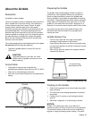
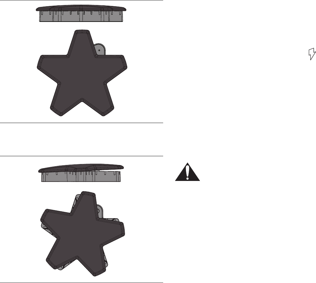
Figure 11 : Correct Burner Cap Placement
Figure 12 : Incorrect Burner Cap Placement


