


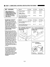
STEP
3:
UNPACKING,
MOVING
AND
PLACING
THE
RANGE
<►
CAUTION:
Proper
equipment
and
adequate
manpower
must
be
used
in
moving
the
range
to
avoid
damage
to
the
unit
or
the
floor.
The
unit
is
heavy
and
rests
on
adjust
able
steel
legs.
•
The
range
has
an
approximate
shipping
weight
as
shown
in
Chart
A.
It
is
recommended
that
the
door(s),
grates,
burner
caps,
front
kick
panel
and
oven
racks
be
removed
to
facilitate
handling.
This
will
reduce
the
weight
as
shown
in
Chart
A
and
allow
the
range
to
pass
through
30"
door
ways.
See
Chart
B
and
Fig.
2a
and
2b.
Do
not
remove
the
grill
or
griddle
assemblies.
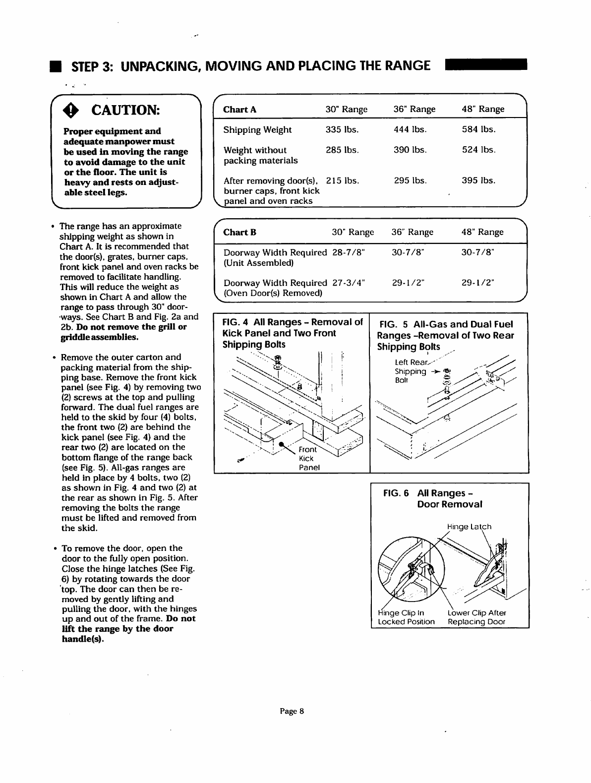
•
Remove
the
outer
carton
and
packing
material
from
the
ship
ping
base.
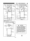
Remove
the
front
kick
panel
(see
Fig.
4)
by
removing
two
(2)
screws
at
the
top
and
pulling
forward.
The
dual
fuel
ranges
are
held
to
the
skid
by
four
(4)
bolts,
the
front
two
(2)
are
behind
the
kick
panel
(see
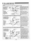
Fig. 4)
and
the
rear
two
(2)
are
located
on
the
bottom
flange
of
the
range
back
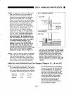
(see
Fig.
5).
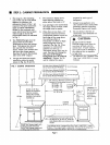
All-gas
ranges
are
held
in
place
by
4
bolts,
two
(2)
as
shown
in
Fig.
4
and
two
(2)
at
the
rear
as
shown
in
Fig.
5.
After
removing
the
bolts
the
range
must
be
lifted
and
removed
from
the
skid.
•
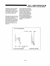
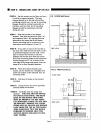
To
remove
the
door,
open
the
door
to
the
fully
open
position.
Close
the
hinge
latches
(See
Fig.
6)
by
rotating
towards
the
door
top.
The
door
can
then
be
re
moved
by
gently
lifting
and
pulling
the
door,
with
the
hinges
up
and
out
of
the frame.
Do
not
lift
the
range
by
the
door
handle(s).
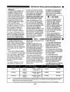
Chart
A
Shipping
Weight
Weight
without
packing
materials
After
removing
door(s),
burner
caps,
front
kick
V
panel
and
oven
racks
30"
335
285
215
Range
lbs.
lbs.
lbs.
36"
444
390
295
Range
lbs.
lbs.
lbs.
48"
584
524
395
Range
lbs.
lbs.
lbs.
J
Chart
B
Doorway
Width
Required
(Unit
Assembled)
Doorway
Width
Required
.
(Oven
Door(s)
Removed)
30"
Range
28-7/8"
27-3/4"
36"
Range
30-7/8"
29-1/2"
48"
Range
30-7/8"
29-1/2"
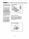
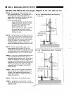
FIG.
4
All
Ranges
-
Removal
of
Kick
Panel
and Two
Front
Shipping
Bolts
Kick
Panel
FIG.
5
All-Gas
and
Dual
Fuel
Ranges
-Removal
of
Two
Rear
Shipping
Bolts
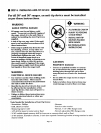
FIG.
6
All
Ranges
-
Door
Removal
Hinge
Latch
Hinge
Clip
In
Lower
Clip
After
Locked
Position
Replacing
Door
Page
8