Page 5
Under the Counter Units —
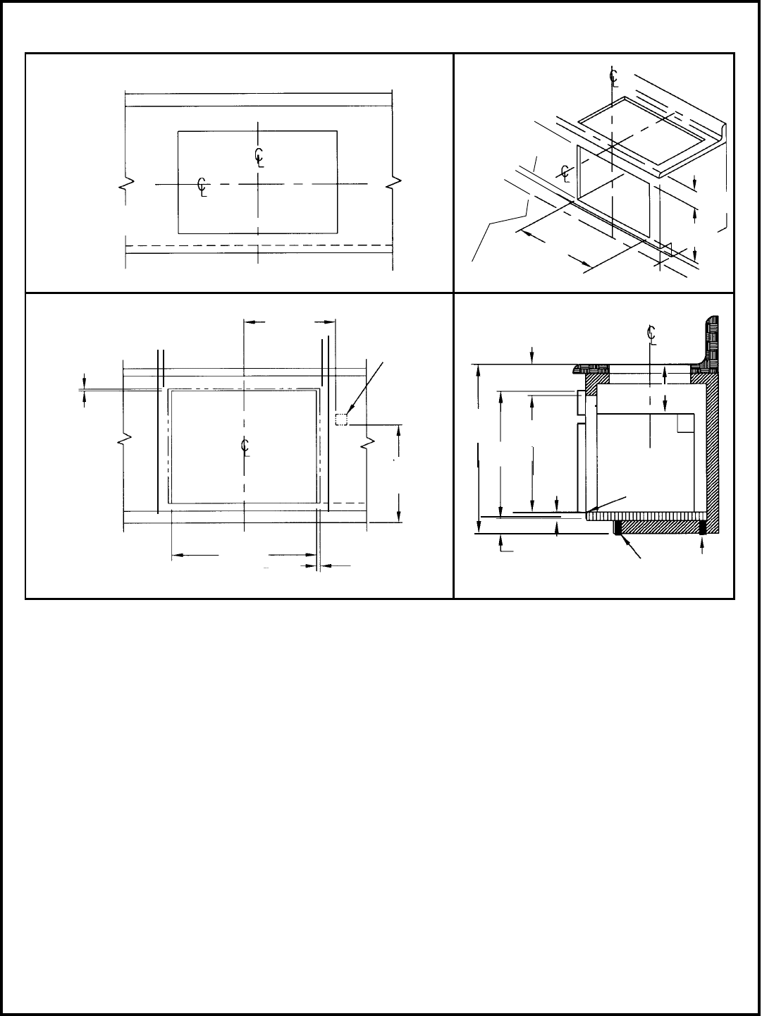
A single oven (S301, SC301, C301 or CM301) installed
under the counter allows for the installation of most
Thermador Gas or Electric non-Cook'n'Vent® Model
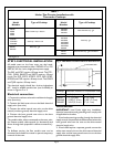
Cooktops. (See Table 1 for recommended cooktop
models.) Downdraft units cannot be installed in
this configuration; Thermador overhead ventilation is
recommended.
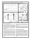
A Thermador cooktop should be installed on the same
center line as the under-the-counter single oven. Follow
the installation instructions provided with cooktop for
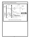
installation of cooktops. Three (3) inches (7.5 cm) minimum
is required from the top of the countertop to the top of the
cutout opening (see Figure 3d) for under-counter installation
with Thermador cooktops (see Table 1, Page 6). If the type
of cabinet or countertop thickness does not provide for this
minimum space, the cabinet base may have to be lowered,
into the toe space, to provide the necessary space above
the oven.
Some TMH cooktops require additional clearances to
combustible walls. Refer to Fig. 4 for specific models and
dimensions.
NOTE:
The Thermador Oven Models
S301, SC301,
C301 or CM301
under the counter and cooktop
combination are a UL and CUL approved installation.
Fig. 3 - Cabinet Cutout - 30" Single Oven Under the Counter Installation
Side-by-side installation units—
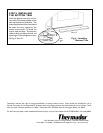
The minimum distance required for side by side installation
is 2 inches (5, 1 cm) from one vertical edge of the cabinet
cutout to the adjacent edge of the next cabinet cutout.
Use only Thermador Trim Piece D30SXSB (black) or
D30SXSW (white) for side-by- side installation in place
of the standard cabinet face between the 2 ovens. This
will leave a 3/4" (2 cm) space from one vertical edge of
the door to the adjacent edge of the other door. Do not
install a cabinet wall partition between the two
ovens.
Cooktop Cutout - See
Cooktop Installation
Instructions
16-1/2"
(41, 9 cm)
Frame Overlap
typ. 5/8" cabinet
(1.5 cm)
Exposed Edge
Must be a
Finish-Cut
Fig. 3a
Fig. 3c
Figure 3d
Frame
Overlap
3/8"
(1, 0 cm)
Cabinet
➛
FRONT VIEW
SIDE VIEW
3" (7,
6
cm) minimum
2x4
(Wall Stud)
Supports
4" (10, 2 cm)
Nominal Toe Space
3/4"
(1, 9 cm)
28-
5
/8"
(72, 7 cm)
4-
1
/8"
(10, 5 cm)
Figure 3b
J-Box
Conduit
28-1/2"
(72, 4 cm)
28-1/2"
(72, 4 cm)
3"
Min.
(7,
6
cm)
CUT OUT
CUT OUT
Floor Line
➛
➛
➛
4" (10, 2 cm) Nominal Toe Space
28-1/4"
(71, 8 cm)
36"
(91 cm)
28-
1
/4"
(71, 8 cm)
18"
(45, 7 cm)


