


4
www.thermastor.com • sales@thermastor.comToll-Free 1-800-533-7533
2.4 Hanging the Quiet-Vent
The Quiet-Vent has four vibration absorbing straps for
hanging from joists, rafters, or trusses (See Fig. 1 & 3)
and use (4) 1/4” diameter lag bolts or the equivalent.
Locate the unit to minimize the ducting from the baths and
kitchen to the Quiet-Vent inlets and from the Quiet-Vent
outlet to the outside. Because the oiling system depends
on gravity, the unit must be oriented with the hanger bolts
on the top.
2.5 Ducting to and from the Quiet-Vent
All flexible ducting connected to the unit should be UL
listed. The preferred method of ducting the exhaust air
from the rooms is to use 4” round duct from 4” x 6”
register heads located in the wall cavities or the ceiling.
For routing through 3.5” stud cavities, flatten the 4”
round duct to 3.25”. If a 4” duct length from a full bath
or kitchen exceeds 50’, two 4” ducts or a 6” duct is
recommended. The 4” duct can be either metal or flexible
and can be routed to the Quiet-Vent 4” inlet or manifolded
to a 6” duct. If more than four 4” ducts are connected to
the Quiet-Vent, use a 6” manifold on the Quiet-Vent’s 6”
inlet.
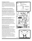
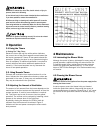
DO NOT locate the register head connecting the kitchen duct to
the Quiet-Vent in the area designated in Fig. 5.
To exhaust the stale air, connect a six inch insulated
flexible duct from the outlet of the Quiet-Vent to a
dampered six inch wall cap. If the length of the exhaust
duct exceeds 50 ft., an 8” duct should be used. All the
ducts must be insulated when they are located in non-
heated space in a cold climate. Flexible duct can be
spliced by threading the ends of the ducts into each
other 3 turns. To reduce leakage, all the duct couplings
should be taped with 3 turns of duct tape. Several ducting
alternatives are illustrated in Fig. 3.
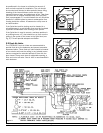
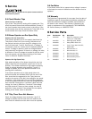
2.6 Wiring the Quiet-Vent
NOTE: All electrical connections must be installed by a qualified
electrician. All wiring must conform to the local electric codes
and/or the National Electrical Code.
Quiet-Vent uses a 115 volt, 10 amp circuit which is
connected to the black and white wires in the electrical
cabinet (see Fig. 4). Spring wound one hour remote timers
or humidity controllers located in the baths and kitchen
are wired in parallel to the two blue wires. These remote
controls activate the high speed of the exhaust fan. These
controls are to be UL listed with minimum electrical ratings
of 2 amps inductive load at 125 VAC.
The prewired 7 day timer located on the Quiet-Vent
activates the low speed of the exhaust fan. The timer can
be mounted remote from the Quiet-Vent. This requires a
double gang electrical box and 3 conductors plus ground
to extend connections to the timer from the Quiet-Vent.
A 4” junction box cover is used to cover the timer opening
on the Quiet-Vent.
Figure 5
Figure 4
Alternative Electrical
Layouts
Circuit to next timer in bath or kitchen
Timer switch ground
115 Volt circuit/ground from
Quite-Vent to bath or kitchen
10-15 AMP 115 Volt
circuit with ground from
main electrical service
Timer switch
ground
Cooking Area
Do Not Install Above or Inside
This Area
Cooking
Equipment
45° 45°
Floor