


6
3. Electrical Connections:
FREE STANDING UNITS: All free standing hot food servers are quipped with a factory installed 36”
(914mm) cord and plug.
• 120V models: Plug conforms to NEMA Standard 5-15P
• 208/240V models: Plug conforms to NEMA
Standard 6-15P
BUILT-IN UNITS: Most units are provided with a 48” exible metal conduit for electrical connections
(see electrical specications for specics).
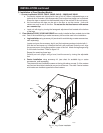
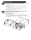
D. Installation of Built-In Units:
All of these units are true built-in models and are designed to be installed into the front face of a counter xture.
Front of units extends beyond the body to form a self-trimming ange that covers the cut out in the xture.
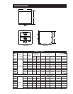
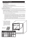
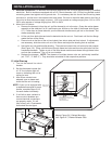
1. Cabinet Cut Out and Support. Cut out the face of the counter xture according to the drawing that is
provided with your hot food server. Figure 2-5 can also be used for the cut out drawing of your model
number. As shown in the drawing allow 1/2” (13mm) minimum cabinet face material above top of cut out
opening. This allows unobstructed seating of hot food server ange.
Be sure
counter xture has adequate depth from front face to inside of back to accept the hot food server.
Minimum depths are shown for each model in Figure 2-5.
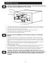
a. The
hot food server body must be supported from the bottom. This can be accomplished by
installing metal support angles of wooden support blocks as shown in Figure 2-5. The supports
are not supplied and must be furnished using a suitable strength metal or wood. The top surface
of these supports must be 1/16” (3mm) below the bottom edge of the face cut out. A metal or
wood crossbrace approximately 2-1/2” (64mm) wide should be securely mounted between the
supports as shown. The center line of the crossbrace must be 4” (102mm) from the face of the
cut out and its top surface must be ush with the side supports.
b. An
alternate support method is to install a solid at platform in lieu of the side supports and
crossbrace. The top surface of the platform must be 1/16” (3mm) below the bottom edge of the
cut out.
INSTALLATION continued
B
A
C
1/2” Minimum
Cut Opening for
Hot Food Server
1/2” Minimum
IL2090-01
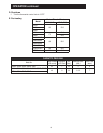
Figure 2-5, Cabinet Mounting
BUILT-IN MODELS OPENING DIMENSIONS
Model “A” Width “B” Height “C” Depth
3A20A
23 3/8” 594 mm
11 1/2” 292 mm
24 1/2” 622 mm
3B20A 22 3/4” 578 mm
3A80A
29 3/8” 746 mm
11 1/4’ 286 mm 20 5/8” 524 mm
3B80A 21 3/4” 552 mm
20 3/4” 527 mm
3C80A 29 1/2” 749 mm
3B84A 22” 559 mm
3C84A 32 3/4” 832 mm
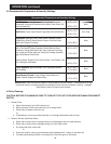
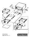
2.
I
nstall Leveling Feet (shown
below). Open the top drawer
and remove the small cloth bag
containing four hex head cap
screws & two mounting screws.
Thread these four screws hand
tight up into the four holes in
the bottom of the unit. Refer to
2-6.
IL2100
Right: Leveling Feet for
Built-in Units.
(pn: 2C-1513D8805)