


VI.
CALIBRATION
OF TIIE
POTENTIOMETER
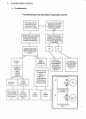
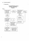
A. Ttoubleshooting
Calibration
of the
potentiometer
is
necessary
only
after replacement
of the
controller
or
if
the
calibra-
tion
plate
should become
jarred
loose
from
its
factory
calibrated position.
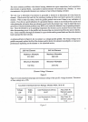
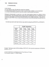
The allowable
temperature
range
of the
gdddle
is
15CPF(65'C)
to
450'F(230.C)
for
each zone.
Within
this temperature
paftrmeterthe
temperature
should
fluctuate
no
more than
+14"F(j'C)
from the
set
point
temperature.
B.
Calibrating
Procedure
Note:Before
making
any calibration
adjustments,
the
griddle
should
be
up
to
temperature
and cycling
and all
panels
including
the front
control
panel
must
be in
their closed position-
Calibrating
the
griddle
with any
of the
panels
open
will
allow
for a
cooler
junction
temperature
at
the connectiorrpoiniof
the
thermocouple
at
the control.
This
may
give
an
inaccurate
indication.
Keeping
the
panelsrclosed
will
provide
for
a more
accurate
calibration
even
though
the
control
does
provide
an ice
point
reference
(calibration)
as
indicated
in
Appendix
A.
A
good
tvpe
K temperature
indicator
source
must
be
used
when
taking
temperature
readings
off
the
griddle
surface for
calibration
adjustrnents.
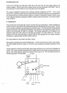
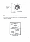
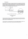
Proper
place-
ment of
the thermocouple
test
probe
is
cmcial.
See Figure
8 for
proper probe
placement
on thr
griddle
surface.
When taking
the temperature
of the
griddle,
the
temperature
probe
should be
placed
at the center
of the
griddle
surface
OF THAI ZONE.
The
temperature
probe
should
be
held down
by an aluminum weight
with
a
piece
of
high
temperature
insulation
(1000
degrees
C) between
the
probe
and
the
weight.
This
combination
helps
to aquire
the most
accurate
readings
possible
without the
weight
absorbing
tempera-
ture
from
the
probe.
1) Determine if
the temperature
of
the center
of
the
griddle
surface
for
that zone
is more than
+14.
F(7"C) above
or
below the
set
point
of 350"F(175"C).
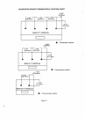
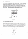
For Steps 2
-7
refer
to figure
9
2) Remove
the temperature
control
knob
to
gain
access to
the calibration
adjustment
screw.
3)
Loosen
the L/2" nut
around
the
potentiometer
shaft and loosen
the calibration
screw but do not
remove.
4)
Turn the
screw in its
slot to
the left
to lower
the
temperature
or to the
right
to raise
the
temperature.
5) Once
proper
calibration
has
been
obtained,
the
call for heat
LED will
illuminate
within 14'F(7'C)
undershoot
and cycle
off
within
14"F(7'C)
of
overshoot.
6)
Tighten the calibration
screw
and the
l/2"
potentiometer
nut
and
paint
the head
of the
calibration
screw and the
area next to
the
screw with
a tamper
proof
shellack.
7)
Replace
the control
knob making
sure
it aligns
with
the 350'dial
indicaror
mark.