6
c. Level the griddle using a carpenter’s level.
Then, rotate the “foot” (hexagonal) portion
of the legs to adjust the griddle to a level
position.
d. Ensure that the griddle is level from front-
to-back and from side-to-side.
D. Electrical Connection
All Accu-Miser Series SS griddles come factory-
equipped with a power cord and plug. The chart
below shows the plug type for each griddle model.
Model Plug type
AM24SS NEMA 15-50P
AM36SS NEMA 15-50P
IMPORTANT
THE ELECTRICAL CONNECTION TO THE
ACCU-MISER REQUIRES A CIRCUIT BREAKER/
FUSED DISCONNECT. THE REQUIRED
RATING OF THE BREAKER VARIES
ACCORDING TO THE MODEL OF GRIDDLE
BEING INSTALLED. REFER TO THE GRIDDLE’S
DATA PLATE, AND TO THE ELECTRICAL
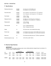
SPECIFICATIONS TABLE (PAGE 2).
CONSULT ALL APPLICABLE NATIONAL AND
LOCAL CODES FOR FURTHER ELECTRICAL
CONNECTION REQUIREMENTS.
1. Before proceeding with the electrical
connections, check the following:
a. Check that the supply wire size is
adequate.
b. Check that the circuit breaker/fused
disconnect is present, and of the correct
rating.
If necessary, refer to the griddle’s data plate and
to the
Electrical Specifications
table (Page 2).
WARNING
ENSURE THAT THE CIRCUIT
BREAKER/FUSED DISCONNECT IS IN
THE “OFF” POSITION BEFORE
PROCEEDING.
2. Insert the power cord plug into its receptacle.
E. Initial Cleaning
WARNING
ENSURE THAT ELECTRICAL POWER
TO THE GRIDDLE HAS BEEN
DISCONNECTED BEFORE CLEANING
THE UNIT.
SECTION 2 - INSTALLATION
1. The surface of the griddle plate is coated with
a rust-preventive material to protect it during
shipment. Clean this material from the griddle
plate with a non-flammable grease solvent.
2. Wash the griddle with warm water and a mild
detergent.
3. Rinse with a damp cloth, then wipe the griddle
dry.
4. Ensure that the griddle is completely dry before
restoring electrical power to the unit.
F. Testing the Installation
IMPORTANT
BEFORE TESTING THE INSTALLATION,
FAMILIARIZE YOURSELF WITH THE ACCU-
MISER OPERATING CONTROLS (SECTION 3A).
1. Ensure that the initial cleaning of the griddle
has been performed, as outlined in Step E
above.
2. Turn all rocker ON/OFF switches to the OFF
position.
3. Rotate all thermostat control knobs
counterclockwise to their lowest temperature
setting.
4. Switch on the circuit breaker/fused disconnect.
5. Perform the following steps for each set of
controls (2 sets for AM24SS, 3 sets for
AM36SS). If any of these tests fail, contact
your Authorized Service Agent.
a. Switch the rocker ON/OFF switch to the
ON position.
b. Rotate the thermostat control knob
clockwise to a setting of 200°F (93°C).
c. Check that the heating indicator light
located beneath the thermostat control
knob illuminates.
d. Wait for a few minutes; then, check that
the zone of the griddle plate that
corresponds to the controls has begun to
heat.
e. Wait for a few minutes to check that the
heating indicator light turns off, showing
that the zone has reached the proper
temperature.
f. Rotate the thermostat control knob back
to its lowest setting. Switch the rocker ON/
OFF switch to OFF.


