


2
ENGLISH
II. INSTALLATION
IMPORTANT
IT IS THE
CUSTOMERS RESPONSIBILITY TO REPORT ANY
CONCEALED OR NON-CONCEALED DAMAGE TO THE FREIGHT
COMPANY.
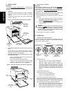
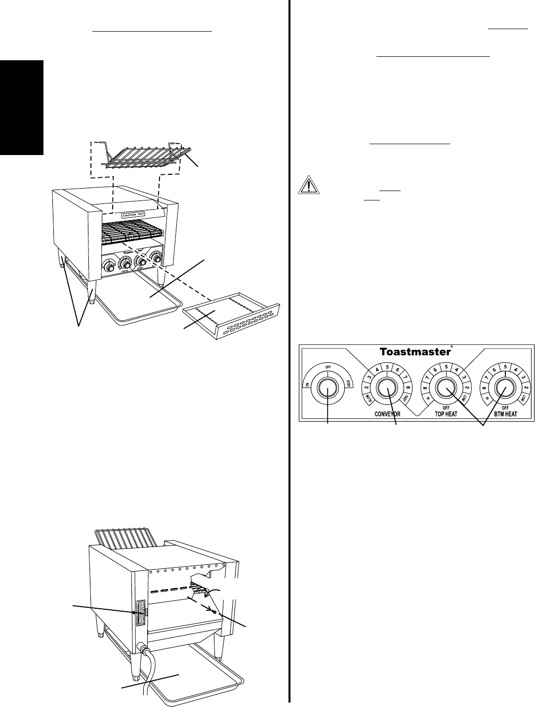
A. Assembly
1. Thread the 4 (102mm) legs into the four holes on the bottom of
the toaster. See Figure 2. Then, place the toaster in the desired
location.
2. Install the entry rack and crumb tray into the front of the toaster,
as shown in Figure 2.
Figure 2 - Basic assembly and front-exit configuration
Legs (4)
thread into holes
in bottom of
toaster
Entry rack
hanger rods fit
into holes on
toaster body
Crumb tray
slides into opening
in front of toaster
Return tray
slides underneath
toaster
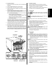
Figure 3 - Electrical connection and rear-exit configuration
3. TOASTERS INTENDED FOR FRONT-EXIT OPERATION
ONLY:
Position the return tray underneath the toaster, as shown in
Figure 2. Note that the return tray extends past the FRONT of
the toaster in the front-exit configuration.
4. TOASTERS INTENDED FOR STRAIGHT-THROUGH, REAR-
EXIT OPERATION ONLY:
Remove the CENTER screw from the rear panel of the
toaster, as shown in Figure 3.
Push the rear panel forward into the toaster.
Position the return tray underneath the toaster as shown
in Figure 3. Note that the return tray extends past the
REAR of the toaster in the rear-exit configuration.
2. Adjust
panel
1. Remove
screw
Return tray
slides underneath
toaster
B. Electrical Utility Connection
IMPORTANT
THE ELECTRICAL CONNECTION TO THE TOASTER
REQUIRES A
CIRCUIT BREAKER/FUSED DISCONNECT. ELECTRICAL SPECIFI-
CATIONS ARE LISTED ON THE SERIAL PLATE (SHOWN IN FIG-
URE 3), AND IN THE
ELECTRICAL SPECIFICATIONS ON PAGE 1
OF THIS MANUAL.
CONSULT ALL APPLICABLE NATIONAL AND LOCAL CODES FOR
FURTHER ELECTRICAL CONNECTION REQUIREMENTS.
1. Before proceeding with the electrical connection, check the
following:
a. Check that the electrical supply matches the toasters
requirements. Refer to the toasters serial plate (Figure 3)
and to the
Electrical Specifications on Page 1.
b. Check that the appropriate receptacle is available for the
power cord plug.
WARNING
ENSURE THAT
BOTH THE CIRCUIT BREAKER/FUSED DIS-
CONNECT
AND THE ON/OFF/STBY KNOB ARE IN THE OFF
POSITION BEFORE PROCEEDING. ENSURE THAT ANY
PACKING MATERIAL RESIDUE HAS BEEN REMOVED FROM
INSIDE THE TOASTING CHAMBER.
2. Insert the power cord plug into its receptacle.
Serial
plate
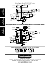
Figure 4
1. ON/OFF/STBY
knob
2. Conveyor
speed control
knob
3. Top and Bottom
temperature
adjustment knobs
III. OPERATION
A. Location and Function of Controls
This section provides a basic description of the toaster controls, their
location, and the functions they perform. The operator MUST be familiar
with the controls. Refer to Figure 4.
1. ON/OFF/STBY knob
When set to ON, turns on the conveyor and elements.
When set to OFF, turns off the conveyor and elements.
When set to STBY, places the toaster in a standby mode
by reducing the power to the heating elements. This saves
power during idle periods and extends the life of the toasters
components. Switching the knob back to the ON position
will return the toaster to operating temperature within 5
minutes.
2. Conveyor Speed control knob
Adjusts the speed of the conveyor belt.
SLOW is the minimum speed setting.
FAST is the maximum speed setting.
3. Top and Bottom temperature adjustment knobs
Adjusts the temperature of the heating elements. Two knobs are
provided so that the top and bottom heating element temperatures
can be adjusted independently. Turning one of the knobs to the
OFF position allows one-sided toasting (for bagels, etc.)
LOW is the lowest temperature setting, which produces a
lighter toasting of the bakery product on its top or bottom.
HIGH is the highest temperature setting, which produces a
darker toasting of the bakery product on its top or bottom.