


5
EXHAUST CANOPY
It is essential that facilities be provided over the griddle to carry off fumes and gases.
However, the unit should not be directly connected to a ue or stack.
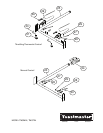
LEVELING UNIT
This griddle is supplied with (4) feet which must be screwed into the legs attached to the
body. Level unit by adjusting the (4) feet which have an adjustment of 1-3/4" (43.75mm) for
accurate and perfect lineup with other units.
DO NOT INSTALL WITHOUT ATTACHING FEET - DO NOT REMOVE FEET.
GAS PIPING
Gas piping shall be of such size and so installed as to provide a supply of gas sufcient to meet
the full gas input of the appliance. If the appliance is to be connected to existing piping, it shall be
checked to determine if it has adequate capacity. Joint compound shall be used sparingly and only
on the male threads of the pipe joints. Such compounds shall be resistant to the action of LP gases.
WARNING: Any loose dirt or metal particles which are allowed to enter the gas lines on this appliance
will damage the valve and affect its operation. When installing this appliance, all pipe and ttings must
be free from loose dirt.
GAS PRESSURE REGULATOR
A convertible pressure regulator is provided with each griddle. It should be connected to the inlet pipe
at the rear of the unit. The gas supply line is then connected to it. It is shipped set for 6" (15.24cm)
water column manifold pressure for use with natural gas.
MANUAL SHUT-OFF VALVE
A manual shut-off valve should be installed upstream from the union and within 6 feet (1.829m) of this
appliance.
PROPANE GAS
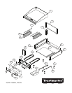
This griddle is equipped with xed orice hoods and is shipped from the factory for use on natural
gas. To convert to propane gas, install the burner orice hoods, located in the grease drawer, as
follows:
1. Remove front panel by removing screws located on the front and the bottom.
2. Remove the burner(s) from the orice hood(s). This is accomplished by removing the burner
mounting screw(s) and sliding the burner(s) off the hood(s).
3. Remove natural gas orice hood(s) and install the propane hood(s) furnished.
4
. Reinstall burner(s).
Note: TMGM & TMGT units use a #47 drill orice for natural gas and a #55 drill orice for
propane.
5. Reinstall front panel.
6. Remove the slotted, or hex-threaded, plug from the pressure regulator. Invert the plug and re-
install. The letters "LP" should now be visible on the plug. The regulator is now set for 10" (25.4cm)
water column.
7. Set
manifold pressure to 10" (25.4cm) water column. A 1/8" pipe plug on the supply pipe can be
removed for attaching a pressure gauge.
CONNECTING GAS SUPPLY LINE
The gas inlet of the griddle is sealed at the factory to prevent entry of dirt. Do not remove this seal
until the actual connection is made to the gas supply line.
CHECKING FOR GAS LEAKS
Soap and water solution or other material acceptable for the purpose shall be used in locating gas
leakage. Matches, candle ame, or other sources of ignition shall not be used for this purpose.
Check entire piping system for leaks.
CAUTION