


Page 13
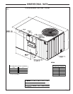
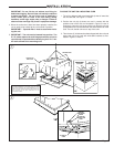
CAUTION: Before making the gas pipe connection give seri-
ous consideration to providing the required clearance neces-
sary to remove the access panels on the unit (e.g., economizer
and filter access panels).
NOTE: In the absence of local codes, the installation must
conform with American National Standard--Z223.1--National
Fuel Gas Code, Latest Revision.
The available gas supply must agree with the required gas supply
marked on the unit nameplate. Minimum permissible gas supply
pressure for purpose of input adjustment must be at least 7.0 in.
w. c. (inches water column) for natural gas and 11 in. w. c. for LP gas.
PIPE DELIVERY SCHEDULE
NOTE: The following procedure and tables below apply to
Natural Gas only.
1. Obtain from the gas company the heating value and specific
gravity of the gas delivered.
2. Determine the exact length of pipe needed.
3. Read BTUH input nameplate on the furnace.
4. Use the multiplier opposite the specific gravity of the gas given
in Table 1 below and insert in the following formula:
CFH =
Furnace Input in BTUH
Gas Heat Content in BTU/Cu. Ft. X Multiplier
TABLE 1
This will give the factor for columns 2 through 6 in Table 2.
GAS PIPING INSTALLATION
7. Read horizontally to the left of this column for the required pipe
size diameter.
5. Using Table 2, select the pipe length nearest to yours.
TABLE 2
6. Follow this line vertically down to the exact CFH found in Step 4
above or the next highest value.
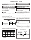
NATURAL GAS ONLY
TABLE OF CUBIC FEET PER HOUR OF GAS
FOR VARIOUS PIPE SIZES AND LENGTHS
PIPE
SIZE
(inch)
LENGTH OF PIPE (feet)
10 20 30 40 50 60 70
1/2 132 92 73 63 56 50 46
3/4 278 190 152 130 115 105 96
1 520 350 285 245 215 195 180
1-1/4 1050 730 590 520 440 400 370
THIS TABLE IS BASED ON PRESSURE DROP OF 0.3 INCH W.C. AND 0.6 SP.GR. GAS
NOTE: If this is an LPG application, consult your LPG supplier
for pipe sizes and deliveries.
GAS PRESSURE SETUP PRECAUTIONS
IMPORTANT: The furnace and its individual shut-off valve
must be disconnected from the gas supply piping system
during any pressure testing of that system at test pressures
exceeding 1/2 psig (3.48 kPa).
The furnace must be isolated from the gas supply piping system by
closing its individual manual shut-off valve during any pressure
testing of the gas supply piping system at test pressures less than
or equal to 1/2 psig (3.48 kPa).
GAS SUPPLY LINE PRESSURE
Before connecting the unit to the gas supply line, be sure to
determine the gas pressure in the line.
If the gas supply pressure is excessive (above 14 inches water
column or 1/2 psig), install a pressure regulator either at the supply
source or in the branch circuit serving the unit. Once the regulator
is installed, set it to provide a pressure of 7 inches water column with
the unit operating and no greater than 14 inches water column with
the unit not firing.
NOTE: Gas pressure in excess of 14 inches water column
(1/2 psig) may damage the regulator, while improper regulation
may result at pressures lower than 5.5 inches water column at
the unit inlet.
If the supply line pressure is below the minimum supply pressure
indicated on the unit nameplate, contact the gas supply company.
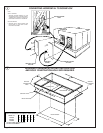
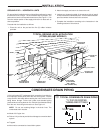
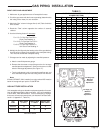
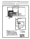
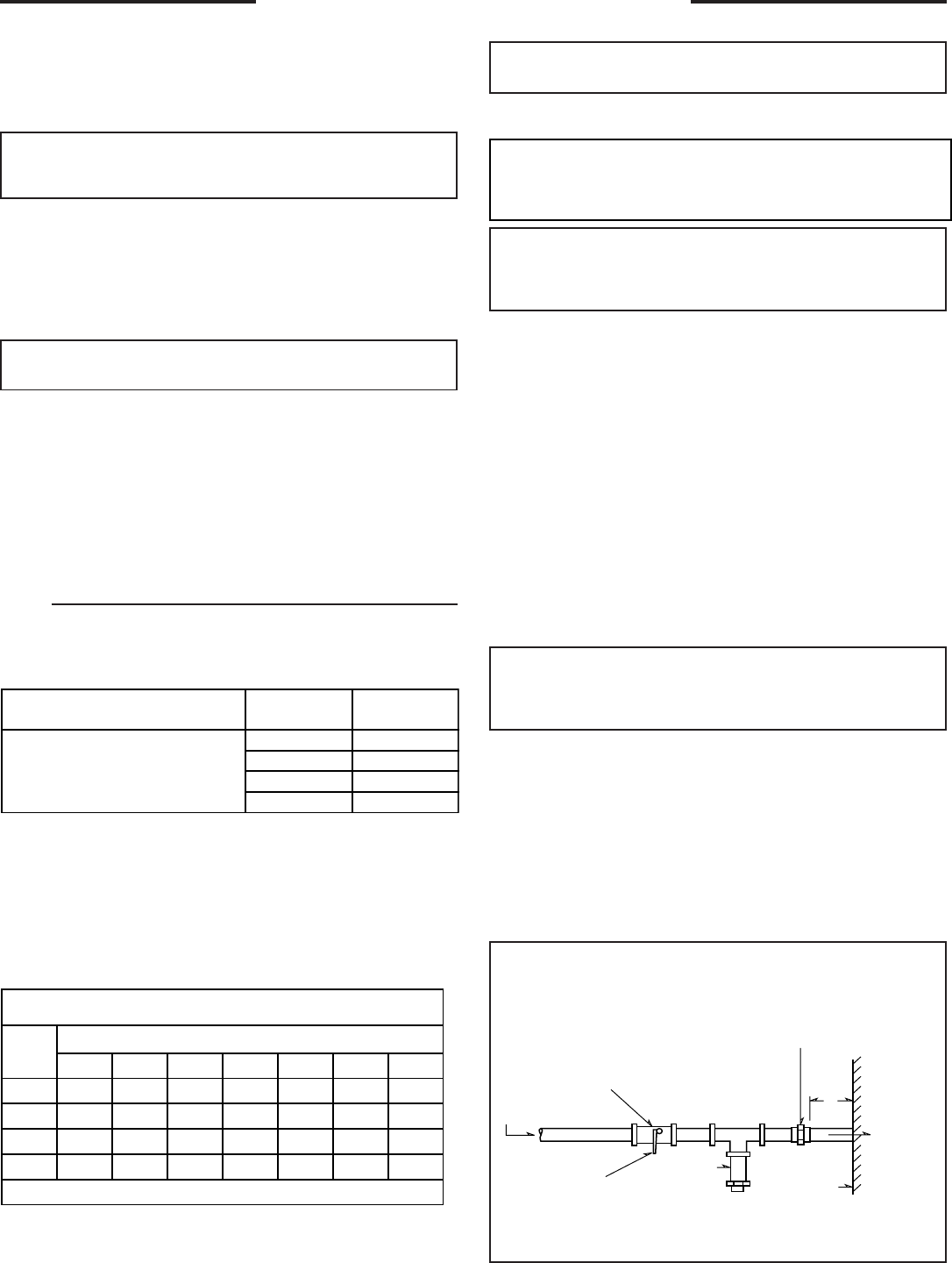
Follow these steps to complete the installation of the unit gas piping.
See Figure 14.
1. Install a tapped, Style A (1/8-inch NPT tap) shut-off gas cock at
the end of the gas supply line near the unit. Be sure the tapped
gas cock is downstream of the pressure regulator, if used.
SPECIFIC
GRAVITY
MULTIPIER
MULTIPIERS TO BE USED
WHEN THE SPECIFIC
GRAVITY OF THE GAS IS
OTHER THAN 0.60
.50 1.10
.55 1.04
.60 1.00
.65 .962
DEALER INSTALLED
GROUND UNION
1/8" N.P.T.PLUGGED
ACCESS FOR TEST
GAUGE CONNECTION
FROM
G
AS SUPPLY
DRIP LEG
FIELD SUPPLIED MAIN
GAS VALVE, MUST BE
INSTALLED BY DEALER
OUTSIDE UNIT.
UNIT
TO MAIN
CONTRO
L
VALVE
6"
MIN
SCHEMATIC DIAGRAM OF
GAS PIPING TO UNIT
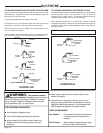
▲WARNING: NEVER USE AN OPEN FLAME
TO TEST FOR GAS LEAKS: AN EXPLOSION COULD
OCCUR, CAUSING INJURY OR DEATH.
r