III. d - SHELF PINS:
The unit is supplied with shelves and shelf pins in-
stalled. Check all shelf pins to assure they are tight-
ened down as they may have come loose during ship-
ping. Rotate the pins clockwise until they are secured
against the side of the cabinet.
III. e - INSTALLING THE CONDENSATE EVAPORATOR:
A bottom-mounted electric condensate evaporator is
normally supplied on all self-contained models. This
is shipped in a cardboard carton secured to the cabi-
net interior, and must be installed prior to use.
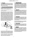
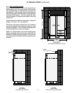
To install a bottom-mounted electric condensate
evaporator (see figure 3).
After the cabinet has been uncrated and the legs/cast-
ers attached, locate the four (4) holes on the exterior
bottom towards the rear of the cabinet. Then, using
the four (4) screws provided, attach the mounting rails
to the cabinet bottom (the end flange is to be up and
be facing towards the cabinet rear). Next, place the
heater into the heater bracket (note the enclosed
springs are only to be used when the heater is placed
on the floor). Slide heater and bracket into the mount-
ing rails. Plug the supplied cord into both the heater
on one end, and the electrical outlet, provided on the
cabinet exterior bottom towards the front, on the other.
Screw the “U-Trap” (UR30LT only) or 90 degree elbow
joint (all other Spacesaver models) into the drain line
located on the rear of the cabinet and then screw the
drain extension into the U-Trap or elbow joint.
A remote model is normally configured for conden-
sate to be run to a floor drain unless purchased with a
condensate evaporator. The installer is responsible
for making the required extension to the floor drain in
accordance with good practice and local regulations.
The bottom mounted electric condensate evaporator
of your Traulsen Spacesaver should be cleaned occa-
sionally to keep it clear of dirt and debris.
-3-
III. INSTALLATION (continued)
III. f - REMOTE INSTALLATION:
Remote models are supplied without compressors,
solenoid valves, etc. The correct voltage, amp listing,
refrigerant and BTU’s are listed on the unit’s serial tag.
It is the responsibility of the installer to specify and
supply the correct size compressor(s) based upon this
information and on-site requirements. Refrigerant line
installation must be done in adhering to good prac-
tice and local regulations. See section “III. e” for in-
formation concerning condensate removal for remote
models.
III. g - CORD & PLUG:
Most self-contained models are supplied with a cord
& plug attached. It is shipped coiled at the top of the
cabinet, secured by a nylon strip. For your safety and
protection, all units supplied with a cord and plug in-
clude a special three-prong grounding plug on the ser-
vice cord. Select only a dedicated electrical outlet with
grounding plug for power source. NOTE: Do not un-
der any circumstances, cut or remove the round
grounding prong from the plug, or use an extension
cord.
III. h -
POWER SUPPLY:
It is recommended that the supply voltage be checked
prior to connection to be certain that proper voltage
for the cabinet wiring is available (refer to the serial
tag to determine correct unit voltage). Make connec-
tions in accordance with local electrical codes. Use
qualified electricians.
Use of a separate, dedicated circuit is recommended.
Size wiring to handle indicated load and provide nec-
essary overcurrent protector in circuit.
III. i - WIRING DIAGRAM:
Refer to the wiring diagram for any service work per-
formed on the unit. Should you require one, please
contact Traulsen Service at (800) 825-8220, and pro-
vide the model and serial number of the unit involved.
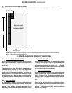
III. j - CLEARANCE:
In order to assure optimum performance, the condens-
ing unit of your Traulsen unit MUST have an adequate
supply of air for cooling purposes. Therefore, the
operating location must either have a minimum of 12”
clearance overhead of the condensing unit or allow
for unrestricted air flow at the back of the unit. Clear-
ance of at least 12” above is required in order to per-
form certain maintenance tasks.
Figure 3
U-Trap
Drain
Extension
Drain
Line
10-32 x 3/8 Screw (4)
Mounting Rails
Electric
Heater
Heater
Bracket
BMCE
Receptacle


