


IV. OPERATION
-7-
V. CARE AND MAINTENANCE:
V. a - CLEANING THE EXTERIOR:
Exterior stainless steel should be cleaned with warm
water, mild soap and a soft cloth. Apply with a damp-
ened cloth and wipe in the direction of the metal grain.
Avoid the use of strong detergents and gritty, abra-
sive cleaners as they may tend to mar and scratch the
surface. Do NOT use cleansers containing chlorine,
this may promote corrosion of the stainless steel.
Care should also be taken to avoid splashing the unit
with water, containing chlorinated cleansers, when
mopping the floor around the unit.
For stubborn odor spills, use baking soda and water
(mixed to a 1 TBSP baking soda to 1 pint water ratio).
V. b - CLEANING THE INTERIOR:
For cleaning the interior, the use of baking soda as
described in section “V. a” is recommended. Use on
breaker strips as well as door gaskets. All interior fit-
tings are removable without tools to facilitate clean-
ing.
V. c - CLEANING THE CONDENSER COIL:
Check the condenser coil periodically. The operating
environment will affect the required frequency of
cleaning. Air must be able to freely circulate through
the condenser. This surface must be kept free of dirt
and grease for proper system operation. Remove
the lower rear panel on the rear of the equipment
cabinet. Carefully clean dirt and lint from the
condenser coil using a vacuum cleaner or soft brush;
do not use a wire brush. Replace the lower rear
panel. Reconnect electrical power supply.
V. d - CONDENSATE REMOVAL SYSTEM CARE:
The evaporator coil, condensate loop and
condensate pan, when needed, can all be flushed
with fresh water by a qualified service technician.
This should be part of any routine maintenance
program and can prolong the life of the equipment.
Condensate removal is provided by evaporation at the
lower rear portion of the equipment cabinet and
does not need a drain. Periodic cleaning of the
condensate removal box may be needed. To access
the condensate removal box, remove the lower panel
at the rear of the equipment cabinet. Clean the
condensate removal box by wiping it out with a clean
damp cloth, using care with the condensate loop
inside. Replace the lower rear panel. Reconnect
electrical power supply.
WARNING: DISCONNECT ELECTRICAL POWER
SUPPLY BEFORE CLEANING ANY PARTS OF THE
UNIT.
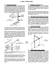
IV. c -
DEFROST CONTROL (CONT'D):
compressor restarts. The next defrost cycle will
start in about 5 hours 40 minutes. On models
ULT27, ULT48 and ULT60, the defrost time control is
located on the right side of the evaporator housing,
behind the temperature control adjustment screw.
On earlier models ULT48 and ULT60, the defrost
time control was accessed through a small round
opening on the outside rear of the unit.
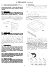
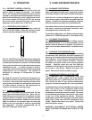
IV. d - REFRIGERATING PRODUCT:
A Thermometer (figure 13) is provided inside all
UHT, ULT & UPT models. Allow the cabinet to reach
normal operating temperature before loading.
UHT, ULT & UPT Series will satisfactorily refrigerate
an assorted load of food items. Allow space between
articles to permit free air circulation. Do not overload
at any one time with warm food products and expect
immediate results. A certain amount of time is
required to remove heat from items before operating
temperatures can be attained. The system is
designed for storage of refrigerated or frozen
product.
Opening the door will increase the temperature in
the cabinet and will require a certain amount of time
to recover. Also, after peak service periods or after
warm product is loaded, the refrigerator will require
a certain amount of time for the temperature to
return to the normal operating range.
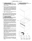
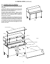
IV. e -
PANS & DIVIDER BARS:
Sandwich Prep models are provided with 1/6 size
plastic pans and metal divider bars. When 18 one-
sixth size pans are ordered, four standard and one
wide pan divider / supports are provided to achieve
appropriate pan separation. When 24 one-sixth size
pans are ordered, six standard and one wide pan
divider bars are provided to achieve appropriate
pan separation. All other arrangements use all
standard width pan divider bars.
°F °C
Fig. 13