


TABLE OF CONTENTS
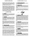
The serial tag is a permanently affixed sticker on
which is recorded vital electrical and refrigeration data
about your Traulsen product, as well as the model
and serial number. This tag is located on the left
interior wall of the compressor compartment, behind
the louvers.
I. THE SERIAL TAG
-1-
FORT WORTH, TX.
SERIAL MODEL
VOLTS Hz PH
TOTAL CURRENT AMPS
MINIMUM CIRCUIT AMPS
MAXIMUM OVERCURRENT PROTECTION AMPS
LIGHTS WATTS
HEATERS AMPS
REFRIGERANT TYPE OZ
DESIGN PRESSURE HIGH LOW
REFRIGERANT TYPE OZ
DESIGN PRESSURE HIGH LOW
370-60294-00 REV (A)
NSF
®
CUS
LISTED
U
L
®
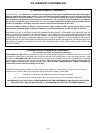
READING THE SERIAL TAG
• Serial = The permanent ID# of your Traulsen
• Model = The model # of your Traulsen
• Volts = Voltage
• Hz = Cycle
• PH = Phase
• Total Current = Maximum amp draw
• Minimum Circuit = Minimum circuit ampacity
• Lights = Light wattage
• Heaters
• Refrigerant = Refrigerant type used
• Design Pressure = High & low side operating
pressures and refrigerant charge
• Agency Labels = Designates agency listings
V. Care & Maintenance
a-Cleaning The Condenser Page 4
b-Hinge Replacement Page 4
c-Replacing The Gaskets Page 4
d-Cleaning The Exterior Page 5
e-Cleaning The Interior Page 5
VI. Misc. Operations
a-Replacing The Shelves Page 5
b-Cleaning The Raised Rail Page 5
VII. Other
a-Service Information Page 5
b-Spare Parts Page 5
c-Warranty Registration Page 5
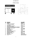
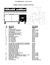
VIII. Parts List Page 6/7/8
IX. Operational Guidelines Page 8
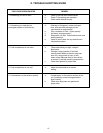
X. Trouble Shooting Guide Page 9
XI. Pan Capacities
a-The VPS System Page 10
b-Pans Page 10
c-Interior Arrangements Page 10
d-Lift-Up Rail Page 10
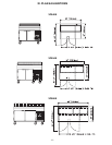
XII. Plan & Elevations Page 11/12
XIII. Warranty Information Page 13
XIV. Index Page 14
I. The Serial Tag Page 1
II. Receipt Inspection Page 2
III. Installation
a-Location Page 2
b-Packaging Page 2
c-Installing Casters Page 2
d-Installing Legs Page 2
e-Cord & Plug Page 2
f-Power Supply Page 2
g-Clearance Page 2
h-Wiring Diagram Page 2
IV. Operation/Start-Up
a-Master Switch Page 3
b-Power Supply Page 3
c-Condensing Unit Page 3
d-Turning The Unit ON Page 3
e-Checking The Temperature Page 3
f-Optional LCD Thermometer Page 3
g-Defrost Timer Page 3
h-Adjusting The Temperature Page 3/4
i-Error Messages Page 4