


TABLE OF CONTENTS
I. THE SERIAL TAG
-1-
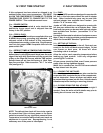
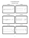
SERIAL MODEL
VOLTS Hz PH
TOTAL CURRENT AMPS
MINIMUM CIRCUIT AMPS
MAXIMUM OVERCURRENT PROTECTION AMPS
LIGHTS WATTS
HEATERS AMPS
REFRIGERANT TYPE OZ
DESIGN PRESSURE HIGH LOW
REFRIGERANT TYPE OZ
DESIGN PRESSURE HIGH LOW
FORT WORTH, TX.
370-60294-00 REV (A)
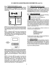
The serial tag is located on the left interior wall
of thecompressor compartment. It contains
vital electrical andrefrigeration data as well as
the model and serial numberof your Traulsen
product.
READING THE SERIAL TAG
• Serial = The permanent ID# of your Traulsen product
• Model = The model # of your Traulsen product
• Volts = Voltage required to operate
• Hz = Frequency in Hertz 60 (U.S.) or 50
(most export units)
• PH = Phase 1
• Total Current = Maximum amp draw
• Minimum Circuit = Minimum circuit ampacity
• Maximum Overcurrent Protection = Maximum
recommended breaker or fuse
• Lights = Light wattage
• Heaters = Amperage of heater(s)
• Refrigerant = Refrigerant type & amount used
• Design Pressure = High & low side design pressures
• Agency Labels = Designate agency listing(s)
I. The Serial Tag Page 1
II. Receipt Inspection Page 2
III. Installation
a-Location & Clearance Page 2
b-Power Supply Page 2
c-Packaging Page 2-3
d-Installing Supports Page 3
e-Installing The Optional Ticket Rail Page 3
f-Optional LCD Thermometer Page 3
g-Installing The Shelves Page 3
h-Installing Optional Overshelves Page 3
IV. First Time Start-Up
a-Power Switch Page 4
b-Cord & Plug Page 4
c-Defrost Timer & Temperature Control Page 4
V. Daily Operation
a-Pans Page 4
b-Setting Up The Rail Page 4
c-Loading The Unit Base Page 4
d-Closing Down The Rail At Night Page 4
VI. Routine Cleaning
a-Cleaning The Rail Area Page 5
b-Cleaning The Cabinet Page 5
c-Shelves & Shelf Pins Page 5
d-Sliding Shelf Cover Page 5
VII. Service & Maintenance Information
a-Cleaning The Condenser Page 6
b-Light Bulb Replacement Page 6
c-Gasket Replacement Page 6
d-Door & Hinge Removal Page 6
e-Front Work Surface Removal Page 7
f-Defrost Timer Page 7
g-Temperature Control Page 7-8
h-Service Information Page 8
i-Wiring Diagram Page 8
VIII. Trouble Shooting Guide Page 9
IX. Operational Guidelines Page 9
X. Pan Capacities
a-The VPS System Page 10
b-Pans Page 10
c-Interior Arrangements Page 10
XI. Spare/Replacement Parts List
a-Standard Rail VPS Models Page 11
b-Jumbo Rail VPS Models Page 11
XII. Adapter Bar Chart Page 12
XIII. Warranty Information Page 13
XIV. Index Page 14