27
The electrical connection should be made
using a double pole isolating switch (cooker
socket) with at least 3mm contact separation
in all poles. The cable must have
conductors of sufficiently high cross-
sectional area to prevent overheating and
deterioration.
The recommended cross-section area is six
square millimetres (6.00mm
2
).
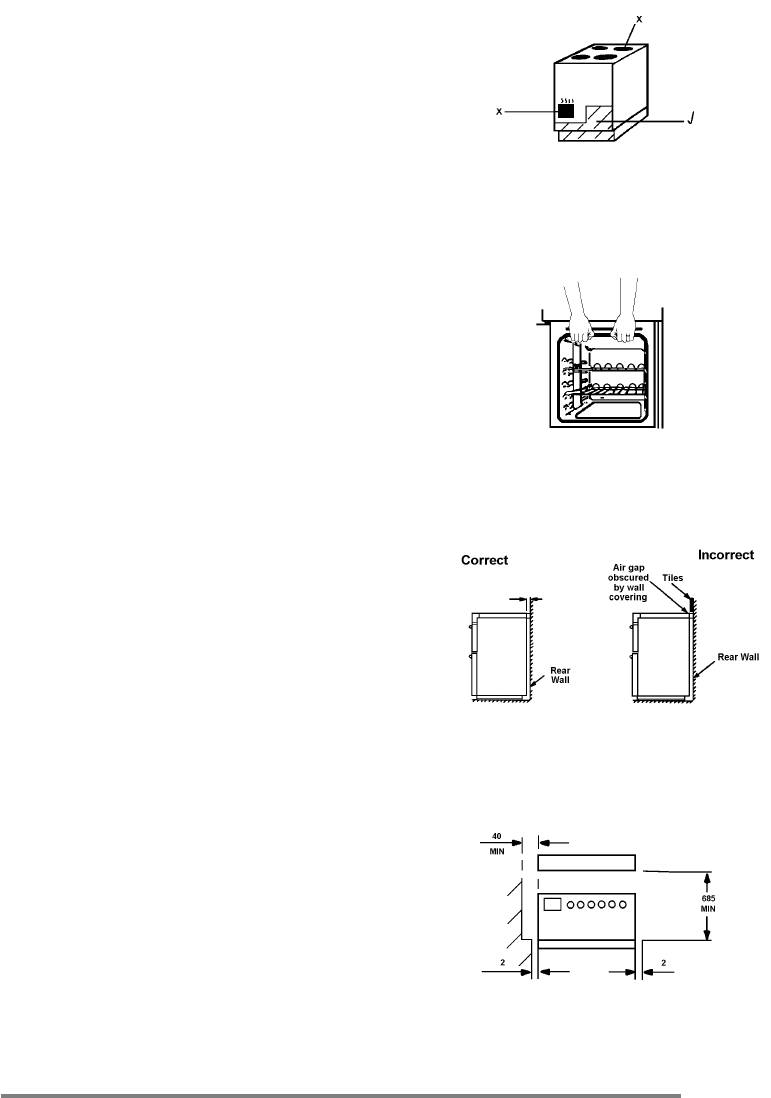
The cable should be routed away from
potentially hot areas marked by X. See
Fig.1.
To move the appliance, open the oven door,
and lift the appliance by holding inside the
top of the compartment. See Fig.2.
This is a type X appliance, which means it is
free-standing and can be fitted with cabinets
on one or both sides.
Side walls which are above hob level should
be protected by heat resistant non-
combustible material and MUST NOT be
nearer than 40mm to the hob side.
A nominal air gap of 2mm at either side of
the appliance is required to enable the
appliance to be moved into position.
Always ensure an air gap is maintained at
hotplate level. Tiles or other forms of deep
wall covering should not obscure this gap.
See Fig.3.
Overhanging surfaces or a cooker hood
should be a minimum of 685mm above the
hob. See Fig.4.
It is important to ensure that the appliance is
level after installation. Levelling feet are
fitted to the appliance to accommodate
uneven floors.
Fig.1.
Fig.2.
Fig.3.
Fig.4
.
Air gap


