


Cook Door
7-5
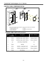
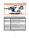
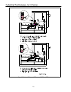
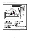
13. Actuator tab should be positioned as shown
in Figure 7-5. It should be parallel to the
primary switch lever. Adjust and bend
(needle nose pliers) actuator tab as
necessary.
14. When the door is closed and the actuator
tab is in contact with the primary and
monitor switches the switches should both
be closed. The actuator tab should be in
contact with the switch paddles such that
when the switches are closed there is about
0.020” of clearance between the switch
paddles and the switch bodies. Also, the
actuator tab should be at or close to
horizontal and be positioned approximately
1/4” from the end of the monitor switch
actuator tab. Adjust the interlock switch
brackets by loosening the screws as
necessary. See Figure 7-5.
15. Once the switches and actuator are
properly adjusted, as the door is opened
the primary switch should disengage before
the monitor switch.
LIMIT SWITCH ADJUSTMENT: SECONDARY
16. Refer to steps 8, 9, 10, and 11 this page.
The trailing arm must be properly engaged
in the cam follower bracket assembly and
the trailing arm guide blocks.
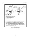
17. Again, the actuator tab should be
positioned as shown in detail of Figure 7-5.
Adjust and bend (needle nose pliers)
actuator tab as necessary.
18. When the door is closed, the actuator tab is
in contact with the secondary switch paddle
and the switch should be closed. There
should be approximately 0.020” of
clearance between the switch paddle and
the switch body. Adjust the limit switch
bracket by loosening the screws as
necessary.
FINAL TESTING OF DOOR SWITCH
ADJUSTMENT:
19. After the door switch assemblies have been
properly aligned and adjusted on both
sides, confirm that with the door closed that
all three switches contacts are closed.
20. As the door is opened slowly confirm that
all three switches operate in the correct
sequence, i.e. as the door is opened the
switches open in the order of primary,
secondary, and then monitor .
21. As the door is slowly closed confirm the
switches close in the opposite order from
above.
22. If the sequencing is not correct, readjust
switch brackets and or associated
hardware until all criteria are met.
SWITCH TEST AT TEMPERATURE:
23. Reinstall main circuit breaker on din rail and
reattach wiring to bottom of circuit breaker.
24. Reattach left side trim piece and magnetron
plenum assembly.
25. Refit top cover and left and right side
covers.
26. Plug the oven in and set the temperature to
525 ᑻF and allow the oven to come up to
temperature and remain at temperature for
15 minutes.
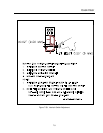
27. Refer to Chapter 5, and put the oven into
test mode. At the bottom left of the screen
are the letters P, S, and M. As the oven
door is slowly opened, the background of
the letters will light up indicating that the
switches have opened.
28. Slowly open and close the door to confirm
the proper sequence of the switches, P, S,
M and M, S, P respectively.
29. If the sequencing is not correct, remove the
left and right side covers and adjust the
switch brackets as necessary and retest the
oven.
30. If the sequencing is correct, while in the test
mode refer to section 9-2 and perform the
microwave radiation leakage tests.