


3-6
Section 3 - Service and Repair
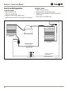
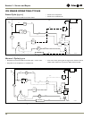
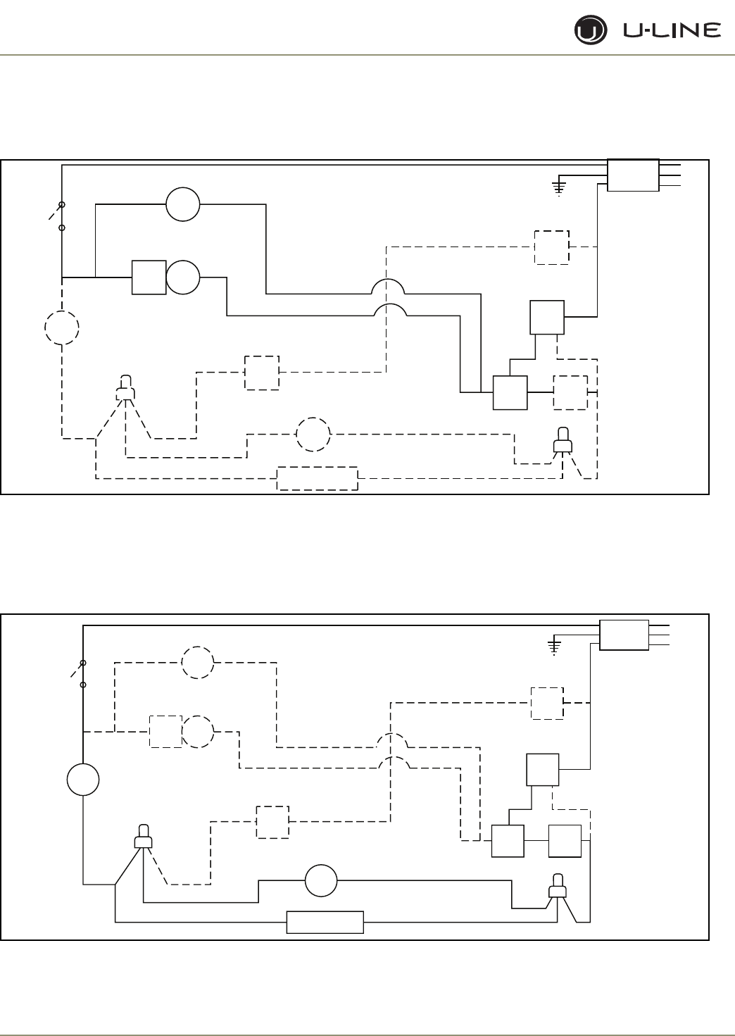
ICE MAKER OPERATING CYCLES
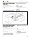
Freeze Cycle (Figure 7)
• Temperature control terminals 2 and 3 are closed.
• Power to the compressor.
• Power to the condenser fan.
Figure 7. Freeze Cycle\
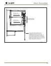
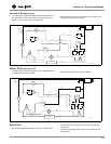
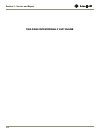
Harvest-1 Cycle (Figure 8
• Temperature control terminals 2 and 3 are open - 2 and 1 close.
• No power to the compressor or condenser fan.
• If bin arm is down, power goes through bin arm switch to the ice
maker motor. If bin arm is up, the ice maker will not harvest.
Figure 8. Harvest-1 Cycle (Hold Switch in Normal Position)
SWITCH
LIMIT
orange
black
black
black
MOTOR
MAKER
ICE
MOLD HEATER
WATER
SWITCH
FILL
C
NC
MOTOR
FAN
LOAD
OVER
black
RELAY
START
COMP.
SWITCH
OFF
ON
black
black
blue
black
CONTROL
TEMP.
NC
black
orange
3
yellow
2
orange
SWITCH
BIN
red
NO
1
C
NO
brown
black
white
C
SWITCH
HOLD
VALVE
WATER
ground
UL183-4
(Hold Switch In Normal Position)
SWITCH
LIMIT
orange
black
black
black
MOTOR
MAKER
ICE
MOLD HEATER
WATER
SWITCH
FILL
C
NC
MOTOR
FAN
LOAD
OVER
black
RELAY
START
COMP.
SWITCH
OFF
ON
black
black
blue
black
CONTROL
TEMP.
NC
black
orange
3
yellow
2
orange
SWITCH
BIN
red
NO
1
C
NO
brown
black
white
C
SWITCH
HOLD
VALVE
WATER
ground
UL183-5