


3-11
Section 3 - Service and Repair
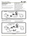
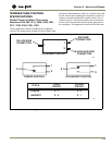
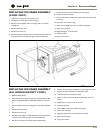
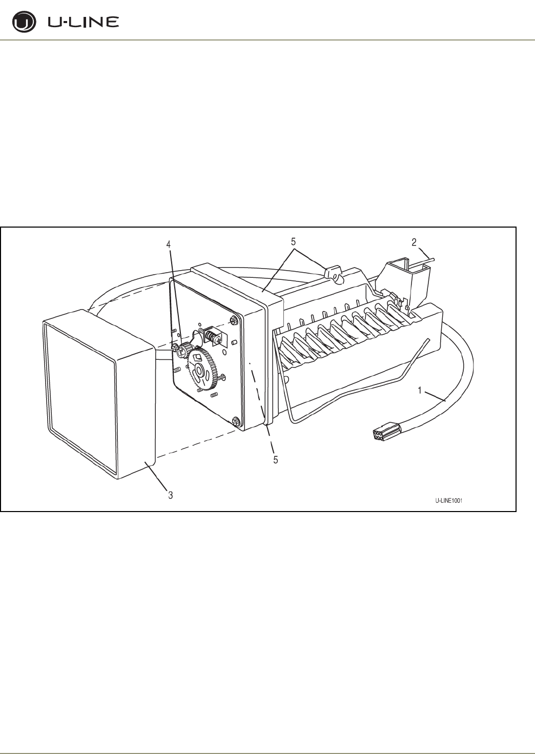
REPLACING ICE MAKER ASSEMBLY
(CO29F ONLY)
1. Unplug the unit from the main power source.
2. Disconnect ice maker wire harness at plug (1).
3. Remove control capillary tube from sensing tube on ice maker
assembly (2).
4. Remove water inlet tube.
5. Remove front cover (3).
6. Advance the ejector blade to the 3 o’clock position by turning the
5/16” hex head on the small brass gear counterclockwise (4).
7. Remove three screws from wall of freezer housing (5).
8. Remove ice maker assembly.
9. Place new ice maker assembly into position and secure with three
screws (5).
10. Reconnect wire harness at plug.
11. Insert control capillary tube into ice maker sensing tube.
12. Insert water inlet tube.
13. Apply Permagum
®
to all exit holes.
14. Install back panel.
15. Plug in unit and test.
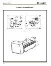
Figure 13. Ice Maker Assembly
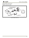
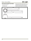
REPLACING ICE MAKER ASSEMBLY
(ALL MODELS EXCEPT CO29F)
1. Remove back panel.
2. Disconnect all wires at bell connectors (5 wires-Models 95, 98 or
SP18; or Plug-Models BI2115, ADA15IM, CO29A or CO1175).
(1)
3. Remove capillary tube from sensing tube on ice maker assembly.
(2)
4. Remove water inlet tube.
5. Remove front cover (3)
6. Advance ejector blades to the 3:00 position by turning the 5/16”
hex head on the small brass gear counterclockwise (4).
7. Remove two screws from the side wall of evaporator(5).
8. Remove three screws from the bottom of the evaporator plate.
9. Remove ice maker assembly from evaporator shelf.
10. Clean alumilastic from evaporator shelf.
11. Apply 1/4” layer of fresh alumilastic to heater side of new ice
maker.
12. Replace parts in reverse order of removal.
13. Reconnect all wires.
14. Insert capillary tube into ice maker sensing tube.
15. Insert water inlet tube.
16. Apply permagum to all exit holes.Mount back panel.
17. Mount the back panel.
18. Plug in unit and test.