Page 6
Recirculation Defrost Module
(Optional - Factory Installed)
The Recirculation Defrost Module is only available
with the 600 cfm and 1200 cfm units. The defrost
cycle is electronically controlled in response to the
outside temperature 23°F to -22°F (-5°C to -30°C).
On a call for defrost, the supply air damper in the
recirculation module closes, exhaust fan is de-energized
and the supply fan continues to recirculate warm air
through the heat recovery core. It is possible to extend
the defrost times during very cold weather by removing
the jumper JU1-F on the circuit board as shown in
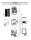
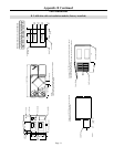
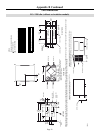
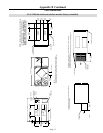
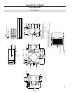
Appendix F. For dimension and weight changes to
the 600 cfm and 1200 cfm models with recirculation
defrost, see Appendix B-2 and B-4.
3.4 Remote Wall Control (Optional)
Remote mounted wall control options can be used
to control the ventilators from a location remote to
the installed unit location. The connection from the
ventilator to the control is low voltage and requires a
4 conductor (24 ga. minimum) LVT cable. Models
are available with either a dehumidistat control or
gas sensor. The following four options are available.
Slide Switch Type
Dehumidistat to engage high speed exchange.
Slide switch operation supporting continuous low
exchange and continuous high exchange.
Push Button Electronic Type
Dehumidistat to engage high speed exchange.
Push-button operation supporting: intermittent
(stand-by) ventilation, continuous low exchange,
continuous high exchange, maintenance indicator
light and exchange indicator light.
Pool Electronic Type
Ideal for pool dehumidification. Dehumidistat to
engage high speed exchange. Push-button operation
supporting: intermittent (stand-by) ventilation, continuous
low exchange, continuous high exchange, maintenance
indicator light and exchange indicator light.
Pollutant Detector Type
Pollutant monitor to engage low/high exchange.
Push-button operation supporting: intermittent
(stand-by) ventilation, continuous low exchange,
continuous high exchange, maintenance indicator
light and exchange indicator light.
4 Airflow Measurement
and Balancing
Once installation is complete, the supply and
exhaust airflows should be balanced. This will
ensure proper operation and a good quality installation.
A well designed duct system with properly sized
duct runs and equal static pressure losses of both the
supply and exhaust will aid in balancing the unit.
However, it will be necessary to take flow
measurements with the proper equipment to ensure a
balanced system.
Magnehelic gauges and Flow Measuring Stations
(FMS) are available for 14" x 8" (356 x 203mm) or
20" x 8" (508 x 203mm) rectangular duct and a range
of round duct sizes. Please ask your supplier for
more information.
4.1 Flow Station Positions
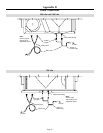
Whether flow stations are permanently installed or
used temporarily, the position they are placed in is very
important to ensure accuracy as shown in Appendix C.
The best locations for mounting the FMS is in the
long straight sections of ducting where airflow has
stabilized across the area of the duct. This position
will provide the most accurate measurements.
The next best location for the FMS is immediately
before or after a 90 degree elbow and 12" (305mm)
from any damper. In straight sections of pipe,
the FMS should be installed at least 30" (762mm)
from any fan outlet. This applies to the "Supply Air
Opening" connection on the heat recovery ventilator
and the "Exhaust Air Opening" connection.
With airflow measuring stations permanently
installed, balancing is done by measuring airflow on
one side of the heat recovery ventilator and then the
other. Adjustments can then be made to the damper
to equalize airflows.
When using the temporary method, an FMS is
installed in one air duct of the heat recovery
ventilator and the flow recorded. The FMS is then
relocated to the other air duct and the airflow is
recorded again. Dampers can then be adjusted to
equalize airflow. This procedure should be repeated
to ensure that the unit is balanced properly.


