


ENGLISH
Installation Manual
16
Conversion for LP or NG Gas
Converting Appliance for Use with LP Gas
WARNING
Conversion is to be performed by a AUTHOR-
IZED SERVICER (or other qualified agency) in
accordance with the manufacturer's instructions
and all codes and requirements of the authority
having jurisdiction. Failure to follow instructions
could result in serious injury or property damage.
The qualified agency performing this work as-
sumes responsibility for this conversion.
WARNING
Electrical power and gas must be turned off
prior to conversion.
If this appliance should be converted for use with gas
LP (propane or butane), each of the following modifi-
cation must be performed:
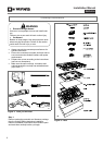
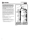
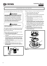
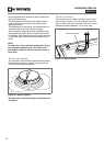
Replace injector on (one ring flame burners)
1. Remove the grates and burner cups.
2. Remove aluminum gas spreader.
3. Loosen injector by turning 9-32” nut driver counter
clockwise.
4. Install the injectors supplied with this appliances in
the appropriate burner. The injectors have small
number stamped on the side, this number codes
the orifice diameter and its correct burner location
(see figure on page 18).
5. Turn clockwise to tighten (tighten to a torque of 15
to 20 inch-lbs).
6. Replace all parts following the reverse order.
7. Save the orifices removed from the appliance
for future use.
017
Figure 17.
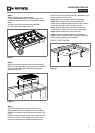
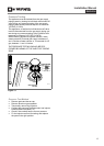
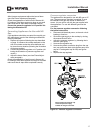
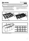
Replace injectors on (two rings flame burner)
1. Remove the grates and burner cups.
2. Remove aluminium gas spreader.
3. Remove the three screws of simmer gas spreader
(1).
4. Remove the two screws of injector cover (2).
5. Loosen injector (A) by turning 9-32” nut driver
counter clockwise.
6. Loosen injector (B) by turning 9-32” box wrench
counter clockwise.
7. Install the injectors supplied with this appliances
in the appropriate burner. The injectors have small
number stamped on the side, this number codes
the orifice diameter and its correct burner location
(see figure of the paragraph “Injectors position”).
8. Turn clockwise to tighten (tighten to a torque of 15
to 20 inch-lbs).
9. Replace all parts following the reverse order.
10. Save the injectors removed from the appli-
ances for future use.
Figure 18.